Sabot for reducing the parasitic weight of a kinetic energy projectile

a kinetic energy and projectile technology, applied in the field of military ordinance, can solve the problems of reducing the stress on the sabot, the energetic parts of the sabot can burn, and the sabot's mass decrease, so as to reduce the force on the energetic sabot, reduce the sabot's mass, and thin out

Inactive Publication Date: 2006-03-21
THE US GOVERNMENT AS REPRESENTED BY THE SEC OF THE ARMY
View PDF8 Cites 10 Cited by
  • Summary
  • Abstract
  • Description
  • Claims
  • Application Information

AI Technical Summary

Benefits of technology

[0014]The energetic sabot of the present invention satisfies this need by allowing selected parts of the sabot to burn away at a controlled rate as it travels up the gun tube. This adds propellant energy (gases) to the gun while at the same time completely supporting the projectile rod. Only selected parts of the sabot are energetic and can burn. The energetic sabot is thicker or larger (the sabot is still the same size as any other standar

Problems solved by technology

Only selected parts of the sabot are energetic and can burn.
However, as

Method used


Image

  • Sabot for reducing the parasitic weight of a kinetic energy projectile
  • Sabot for reducing the parasitic weight of a kinetic energy projectile
  • Sabot for reducing the parasitic weight of a kinetic energy projectile

Examples


Embodiment Construction

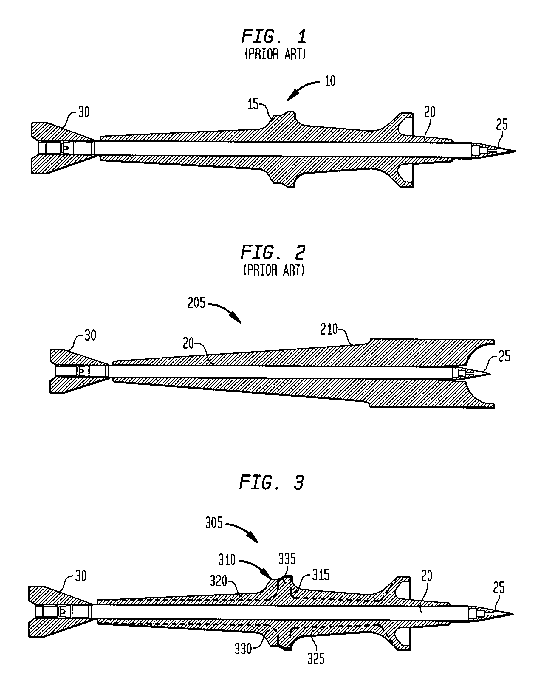
[0025]FIG. 1 is a cut-away profile view of a prior art kinetic energy tactical projectile 10 using a standard sabot 15. The kinetic energy tactical projectile 10 is comprised of a sabot 15, a projectile rod 20, a nose 25, and a fin 30. FIG. 2 is a cut-away profile view of a prior art kinetic energy tactical projectile 205 using a puller sabot 210. The kinetic energy tactical projectile 205 is comprised of a puller sabot 210, a projectile rod 20, a nose 25, and a fin 30.

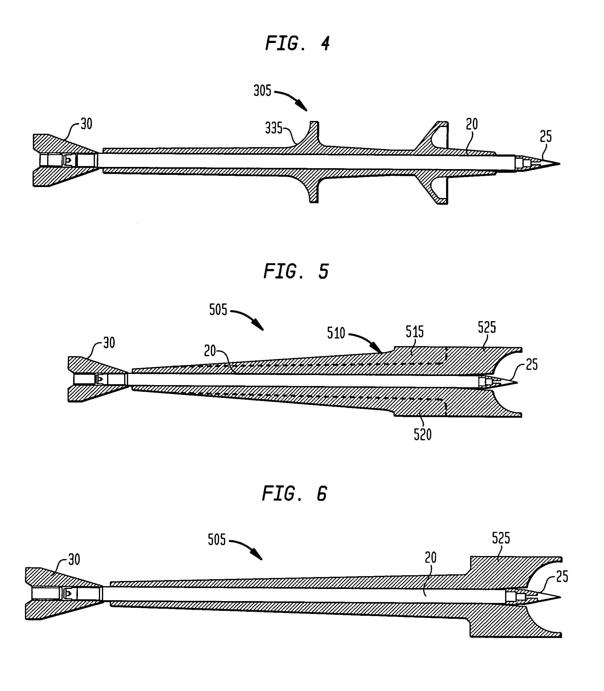
[0026]FIG. 3 and FIG. 4 are cut-away profile views of a kinetic energy projectile 305 with an energetic pusher sabot 310. FIG. 3 illustrates the size of the energetic pusher sabot 310 needed for shot start. Energetic regions 315, 320, 325, 330 are the part of the energetic pusher sabot 310 no longer needed for support as the energetic pusher sabot 310 travels up the gun tube (not shown). After energetic regions 315, 320, 325, 330 are burned away, the energetic pusher sabot 310 is reduced to the pusher sabot base 335. ...


PUM


Abstract

An energetic sabot allows part of the sabot to burn away at a controlled rate, adding propellant energy to the gun while at the same time completely support the projectile rod. The energetic sabot is thicker or larger at shot start to support the projectile without breaking. As the energetic sabot travels up the gun tube, the energetic sabot then thins out or otherwise decreases in mass as the force on the energetic sabot decreases. The weight of the projectile consequently decreases as it travels up the gun tube, allowing the gun gases to push a lighter projectile, giving the projectile a higher velocity. Due to its continually decreasing weight in the gun tube, the projectile experiences greater acceleration and exits the gun with a higher muzzle velocity. A secondary effect comes from increased pressure in the gun tube from the gases relinquished in the burning of the sabot, further increasing the velocity of the projectile. This higher velocity in turn leads to greater projectile velocity at target impact, and thus a greater penetration depth. The energetic sabot is “doped” with energetic materials by sprinkling either explosive, propulsive, or pyrotechnic agents between layers of the composite material in the energetic sabot. These agents ignite upon propulsion; their composition is determined from their burn rates. The burn rate may be designed proportional to the decrease in chamber pressure; the less pressure in the tube, the more material that can be relinquished.

Description

FEDERAL RESEARCH STATEMENT[0001]The invention described herein may be manufactured and used by or for the Government of the United States for governmental purposes without payment of any royalties thereon.BACKGROUND OF INVENTION[0002]The present invention generally relates to the field of military ordinance. In particular, it relates to a new sabot design for use in Kinetic Energy (KE) projectiles, which reduces the parasitic weight of the sabot upon launch and transforms the parasitic weight into propulsion gases that provide a greater velocity to the projectile.[0003]Kinetic Energy (KE) projectiles are well known in the ammunition community and are made in small, medium and large caliber from 20 to 120 mm. FIGS. 1 and 2 illustrate cross sectional views of KE projectiles 10 and 205 with two types of sabots 15 and 210. The standard sabot 15 (also referenced as pusher sabot 15) is illustrated in FIG. 1, and the puller sabot 210 is illustrated in FIG. 2. Both the standard sabot 15 and...

Claims


Application Information

Patent Timeline
IPC IPC(8): F42B14/06
CPCF42B14/068F42B14/061
Inventor SEBASTO, ANTHONYGILMAN, STEWARTMANOLE, LEONPALATHINGAL, MOHANMARCHAK, ROBERT
Owner THE US GOVERNMENT AS REPRESENTED BY THE SEC OF THE ARMY
Why Eureka
Try Eureka