Sleep apnea treatment apparatus

a technology for sleep apnea and treatment equipment, which is applied in the direction of mechanical equipment, valves, operating means/releasing devices, etc., can solve the problems of hypersomnolent sleep apnea patients hypersomnolent sleep apnea patients may be at risk for excessive mortality, and may be at risk for accidents while driving and/or operating potentially dangerous equipment, etc., to achieve easy operation and reduce pressure

Inactive Publication Date: 2006-03-21
RIC INVESTMENTS LLC
View PDF37 Cites 116 Cited by
  • Summary
  • Abstract
  • Description
  • Claims
  • Application Information

AI Technical Summary

Benefits of technology

[0029]A particular advantage of the present invention is that the unique ramp circuitry enables not only an initial ramp cycle to be achieved for when one first attempts to sleep but such circuitry also permits one or more additional cycles to be selectively activated by the user at instances where the user awakens during an extended rest period, or when the user fails to fall asleep during the first ramp cycle and again requires a ramp cycle to fall back to sleep, or even within (i.e., during) an already ongoing ramp cycle. Typically, during a sleeping period of several hours, the time required to once again fall asleep after briefly being awakened is generally less than the time spent initially falling asleep. To accommodate this phenomenon, the ramp circuitry of the instant invention allows adjustment of the ramp time of any additional ramp cycle to run for a selected fraction of the initial ramp time, which itself may be a pre-programmed, patient-selected a clinician-selected fraction of a prescription time preset by a health care professional in supervision of the patient's sleep apnea treatment.
[0030]The ramp circuitry enables a physician or other health care worker to set the initial ramp time(s) and prescription pressure(s). Additionally, however, the novel ramp circuitry of the present invention permits adjustment of the “shape” of the pressure ramp curve, whereby the physician, health care worker or patient can suitably manipulate appropriate controls associated with the ramp circuitry to control the pressure output pattern of the ramp (as represented as a function of pressure versus time) such that it may assume virtually any configuration including, inter alia, linear, stepped, or curvilinear slope, depending upon a patient's particular needs as dictated by the results of the patient's sleep study. In the case of bi-level systems according to the instant invention, the ramp circuitry also affords, for example, simultaneous, independent, identical or differential ramping of IPAP and EPAP. Alternatively, the parameters establishable by the ramp circuitry may also be preprogrammed by the manufacturer.
[0031]Additionally, sufferers of sleep apnea are sometimes afflicted by other maladies which limit the degree to which they may safely physically exert themselves. An advantage of the present invention is that it enables a limited-mobility user, at his discretion, to operate the apparatus either by manual controls located directly on the apparatus or via remote control. Equally as important, it provides any sleep apnea sufferer using the apparatus with the peace of mind of knowing that the pressure can be reduced at any time via the remote control. Further, the preferred embodiment of the remote control contemplated for use in the present invention is one which the user can operate easily and reliably either in light or darkness to turn the apparatus on and off as well as selectively activate the first or subsequent ramp cycles.
[0032]As additional or alternative design features, the apparatus may include an automatic ON / OFF mechanism and / or alternative ramp activation means.
[0033]The automatic ON / OFF mechanism desirably comprises a sensor means situated within or proximate to the patient's breathing circuit. Such breathing circuit will be understood to include, but is rot limited to, the gas flow conduit, the gas flow generator means and the respiratory interface, e.g., oral mask, nasal mask, oral / nasal mask, endotracheal tube, nasal cannulae, or other suitable appliance. The sensor means may assume the form of a pressure, flow, thermal, audio, optic, electrical current, voltage, force, displacement or other suitable transducer which detects the presence (and / absence) of the patient. More particularly, according to a first mode of operation, when the respiratory interface is appropriately positioned over the patient's face, the sensor means will operate so as to detect at least one of the above-mentioned conditions indicative of the patient's presence and generate a signal that is transmitted to the flow generator to activate the apparatus. In a second mode of operation, the sensor means may be designed solely for apparatus activation purposes. Hence, upon removal of the respiratory interface, the sensor means would fail to detect any conditions indicative of the patient's presence and, therefore, generate an appropriate signal to deactivate the apparatus. A third mode of operation combines these functions. That is, the sensor means may be operable to detect both the presence and absence of the patient and generate a signal to activate the apparatus upon detection of a condition indicative of the patient's presence, as well as an apparatus deactivation signal upon failure of detecting such a condition, i.e., the patient's absence.
[0034]The alternative ramp activation means may comprise a sensor means responsive to signals of selected magnitude and / or frequency consciously produced by the patient. In accordance with a presently preferred embodiment, the alternative ramp activations means may comprise a pressure transducer, for instance, a microphone located within or near the patient's respiratory interface, associated gas flow conduit or gas flow generator and capable of detecting sound of a limited frequency range spanning that associated with human speech. So configured, the transducer would be nonresponsive to common ambient sounds produced by the user (e.g., coughing or sneezing), machinery noise, music or animal sounds. Moreover, by being isolated through its enclosure within the gas flow system, the transducer would detect only the patient's speech to the exclusion of others in the vicinity or speech emanating from television or radio sources. Upon detection of the patient's speech such as, for example, when the patient awakens and speaks to start a new ramp cycle, the audio transducer generates and transmits an activation signal to the ramp circuitry to initiate the desired ramp cycle. The sensor may alternatively be operable to begin a ramp cycle in response to detection of a predetermined pattern of inhalations and / or exhalations or other conscious actions by the patient.

Problems solved by technology

Those afflicted with sleep apnea experience sleep fragmentation and intermittent, complete or nearly complete cessation of ventilation during sleep with potentially severe degrees of oxyhemoglobin desaturation.
Hypersomnolent sleep apnea patients may be at risk for excessive mortality from these factors as well as by an elevated risk for accidents while driving and / or operating potentially dangerous equipment.
Such abnormalities may include narrowing of the upper airway due to suction forces evolved during inspiration, the effect of gravity pulling the tongue back to appose the pharyngeal wall, and / or insufficient muscle tone in the upper airway dilator muscles.
These treatments constitute major undertakings with considerable risk of postoperative morbidity if not mortality.
Pharmacologic therapy has in general been disappointing, especially in patients with more than mild sleep apnea.
In addition, side effects from the pharmacologic agents that have been used are frequent.
Although mono-level positive airway pressure or CPAP has been found to be very effective and well accepted, it suffers from some of the same limitations, although to a lesser degree, as do the surgery options; specifically a significant proportion of sleep apnea patients do not tolerate CPAP well.

Method used


Image

  • Sleep apnea treatment apparatus
  • Sleep apnea treatment apparatus
  • Sleep apnea treatment apparatus

Examples


Embodiment Construction

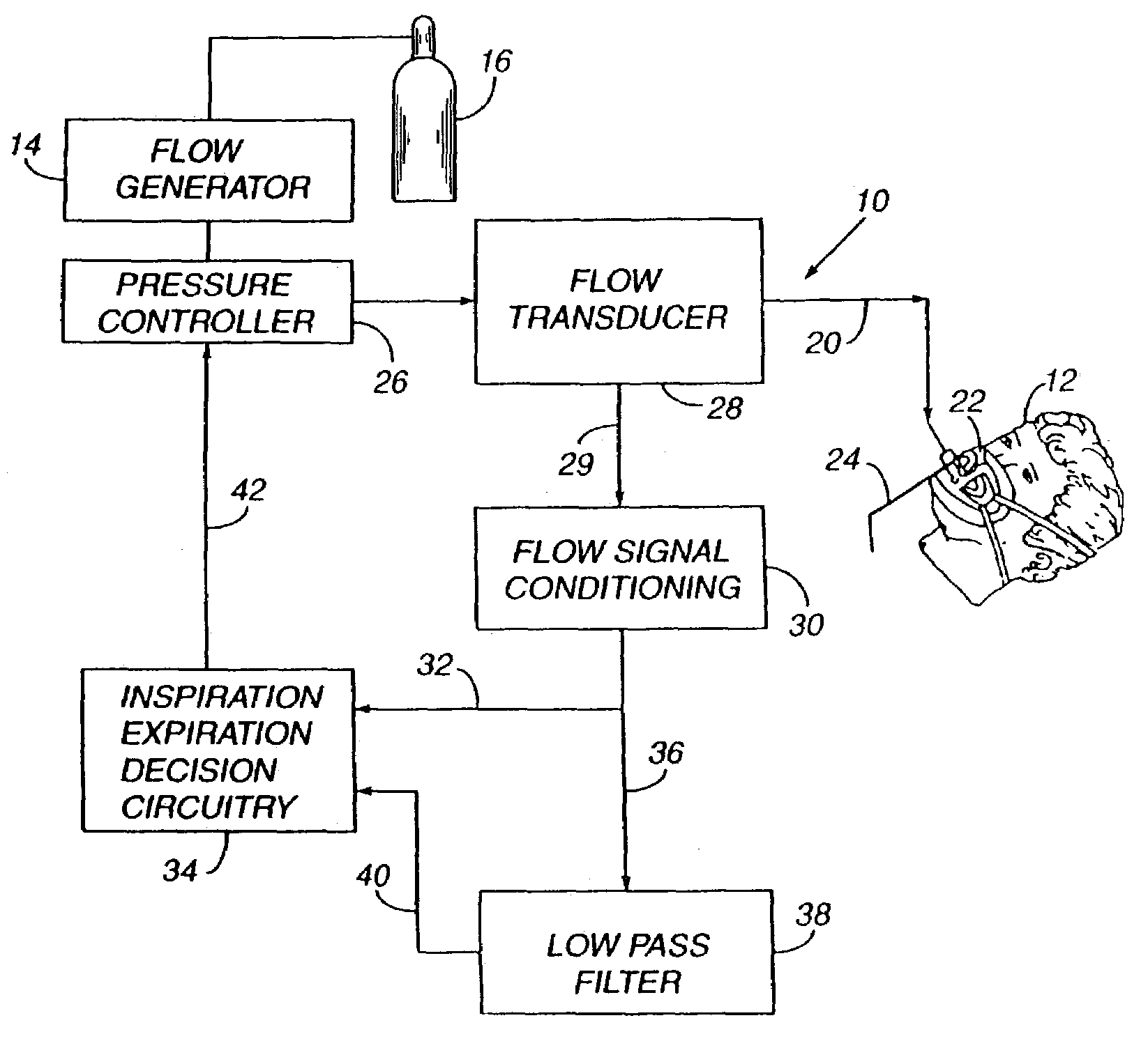
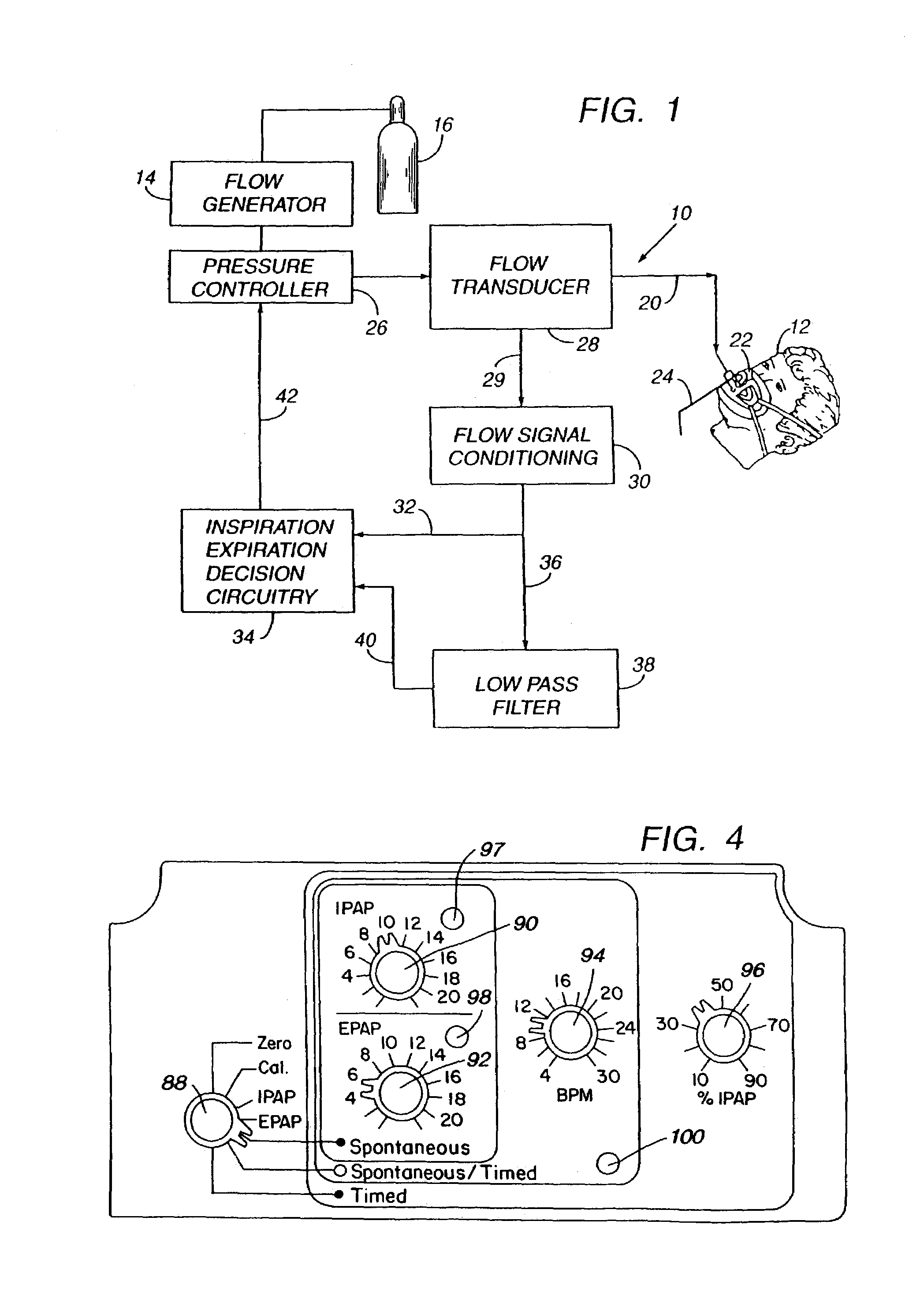
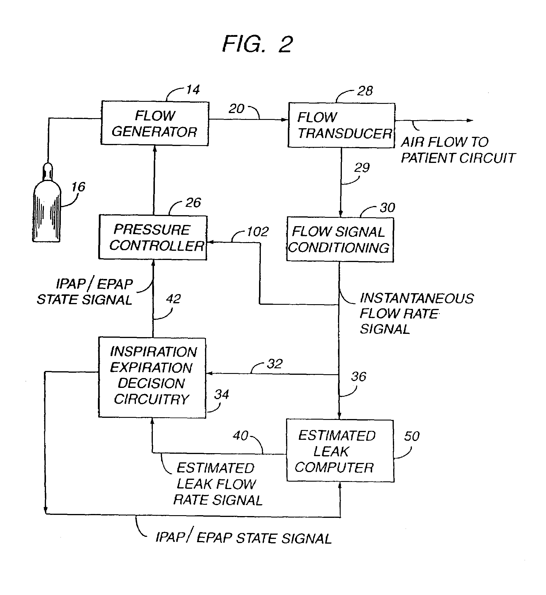
[0064]There is generally indicated at 10 in FIG. 1 an apparatus according to one presently preferred embodiment of the instant invention and shown in the form of a functional block diagram. Apparatus 10 is operable according to a novel process which is another aspect of the instant invention for delivering breathing gas such as air alternately at relatively higher and lower pressures (i.e., equal to or above ambient atmospheric pressure) to a patient 12 for treatment of the condition known as sleep apnea.

[0065]Apparatus 10 comprises a gas flow generator 14 (e.g., a blower) which receives breathing gas from any suitable source, a pressurized bottle 16 or the ambient atmosphere, for example. The gas flow from flow generator 14 is passed via a delivery conduit 20 to a breathing appliance such as a mask 22 of any suitable known construction which is worn by patient 12. The mask 22 may preferably be a nasal mask or a full face mask as shown. Other breathing appliances which may be used i...


PUM


Abstract

Improved methodology and apparatus for the clinical study and treatment of sleep apnea which incorporates one or more of the following features: (1) application of mono-level, alternating high and low level, or variable positive airway pressure generally within the airway of the patient with the mono-level, high and low level, or variable airway pressure generally being coordinated with and/or responsive to the spontaneous respiration of the patient, (2) usage of adjustably programmable pressure ramp circuitry capable of producing multiple pressure ramp cycles of predetermined duration and pattern whereby the ramp cycles may be customized to accommodate the specific needs of an individual sleep apnea patient so as to ease the patient's transition from wakefulness to sleep, (3) remote control or patient-sensed operation of the apparatus, (4) employment of safety circuitry, reset circuitry and minimum system leak assurance circuitry, controls and methods, and (5) utilization of clinical control circuitry whereby sleep disorder data may be compiled and appropriate therapy implemented during a one-night sleep study.

Description

CROSS REFERENCE TO RELATED APPLICATIONS[0001]This application is a Continuation of U.S. patent application Ser. No. 09 / 393,003 filed Sep. 9, 1999, now U.S. Pat. No. 6,629,527, which is a Continuation of U.S. patent application Ser. No. 08 / 677,320 filed Jul. 2, 1996, now U.S. Pat. No. 5,970,975, which is a Continuation of U.S. patent application Ser. No. 08 / 110,372 filed Aug. 23, 1993, now U.S. Pat. No. 5,551,418, which is a Continuation-In-Part of U.S. patent application Ser. No. 07 / 786,269 filed Nov. 1, 1991, originally issued as U.S. Pat. No. 5,239,995 and now reissued as U.S. Pat. No. Re. 35,295.FIELD OF THE INVENTION[0002]The present invention relates generally to methodology and apparatus for treatment of sleep apnea and, more particularly, to mono-level, bi-level and variable positive airway pressure apparatus, as well as feedback type versions thereof, including circuitry for enabling a patient to selectively actuate one or more pressure ramp cycles wherein, during each ramp ...

Claims


Application Information

Patent Timeline
Patent Type & Authority Patents(United States)
IPC IPC(8): A61M16/00
CPCA61M16/00A61M16/0069A61M2016/0021A61M2205/3561A61M2016/0039A61M16/0051A61M16/024
Inventor ESTES, MARK C.CATTANO, JANICE M.
Owner RIC INVESTMENTS LLC
Why Eureka
Try Eureka