
Silica fine particle, toner, two-component developer and image forming method

a technology of toner and silicon, applied in the direction of instruments, silicon compounds, silicon oxides, etc., can solve the problems of difficult downsizing affecting the durability and stability of the whole apparatus, and the surface of the photosensitive member is apt to wear away, so as to prevent fogging, excellent transferability, and excellent durability and stability

Active Publication Date: 2006-03-21
CANON KK
View PDF38 Cites 48 Cited by
  • Summary
  • Abstract
  • Description
  • Claims
  • Application Information

AI Technical Summary

Benefits of technology

[0032]It is another object of the present invention to provide a toner which has excellent transferability, prevents the occurrence of fogging and is excellent in durability and stability even when the toner is used to continuously print a large number of copies, as well as an image forming method.
[0033]It is still another object of the present invention to provide a toner which rarely contaminates a charging roller, can form a clear image and is excellent in endurance stability even when the toner is used to continuously print a large number of copies, as well as an image forming method.
[0034]It is a further object of the present invention to provide a toner which hardly wears an image bearing member and is excellent in image density stability, as well as an image forming method.

Problems solved by technology

However, since a member used for cleaning is pressed against the surface of the photosensitive member, the surface of the photosensitive member is apt to wear away.
Since the apparatus is provided with a cleaning unit, the apparatus becomes bulky inevitably, which is an obstacle to the downsizing of the apparatus.
However, when a cleaner-less system is attained by preventing the formation of a pattern with the residual toner, a device for applying a voltage to a member for preventing the formation of a pattern is required, thereby making it difficult to downsize the whole apparatus.
However, the publication is utterly silent about physical properties of the toner, particularly an external additive existent on the surface of the toner, which are the major factors of the fusion of the toner to a member or drum, or the like.
However, the publication is utterly silent about the physical properties of the toner, particularly an external additive existent on the surface of the toner.
However, this application does not refer to a coarse particle contained in the silica fine particle used as the external additive.
When the silica fine particle contains a large amount of the coarse particle, the problem of contamination of a roller or an image bearing member in the image forming comprising a charging roller as a charging member.
However, when corona discharge is used, ozone is generated.
Further, as the resistance value of the charging roller is changed by environmental variations, it has been difficult to control the potential of the photosensitive member to a desired value.
Further, the generation of vibration and noise (to be referred to as “AC charging sound” hereinafter) in the charging member and the photosensitive member caused by the electric field of an AC voltage and the deterioration of the surface of the photosensitive member by discharge become marked as new problems to be solved.
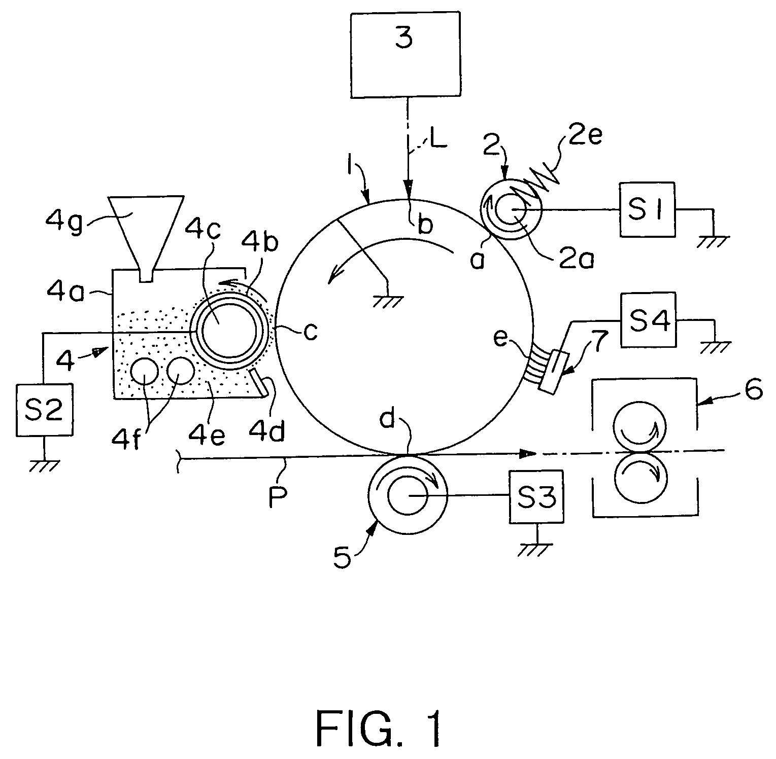
When a “development / cleaning system” or “cleaner-less” technology is used, the transfer residual toner cuts off exposure light and interferes with the formation of an electrostatically charged latent image, thereby making it impossible to control the potential to a desired value, with the result of the formation of a negative memory on an image.
Even when a member for preventing the formation of a pattern is used, image quality tends to lower.
However, it has been confirmed that when the toner containing the above externally added inorganic fine particles each having a small particle diameter is used for a long time, the inorganic fine particles each having a small particle diameter are buried in the surface of the toner by stress from a carrier when the toner is used as a two-component developer, stress from a developer coating blade or developer supply roller when the toner is used as a one-component developer, or collision with an inner wall of a developing device or stirring blade, or between toners.
However, a toner to which inorganic fine particles each having a small particle diameter and silica having a large particle diameter are externally added is apt to cause a so-called “charge-up” that charging properties become too high in a low-humidity environment.
Thus, the toner has poor environmental stability.
Although this toner achieves excellent environmental characteristics in a two-component developer containing a carrier, the hydrophobic silica having a particle diameter of 15 to 20 nm separates from the surface of the toner in a non-magnetic one-component developer, thereby making it impossible to obtain a satisfactory spacer effect and promoting the silica to be buried in the surface of the toner.
As a result, an increase in fogging, the occurrence of a cleaning failure and a reduction in transfer efficiency are seen.
Although this method roughly indicates the size of a particle, it is difficult to know the size of a primary particle and the particle diameter of a particle of higher order, which is an agglomerate of primary particles, even when their specific surface areas are the same.
In this measurement method, the measurement range is so narrow that particles larger than the aperture diameter cannot be measured and particles each having a small particle diameter of about 1 μm or less cannot be measured owing to detection limits.
Therefore, it is difficult to know the particle diameter, and further improvement in the control of a particle diameter distribution is required.

Method used


Image

  • Silica fine particle, toner, two-component developer and image forming method
  • Silica fine particle, toner, two-component developer and image forming method
  • Silica fine particle, toner, two-component developer and image forming method

Examples


production example 2

FOR ORGANIC FINE POWDER

[0324]Hydrophobic treatment was carried out on the crude silica in Production Example 1 at a slightly lower temperature than that in Production Example 1. And then cracking, classification, and the control of particle diameter were carried out to obtain silica fine particles (3) (number average length of primary particles of 40 nm, actually measured BET specific surface area of 72 m2 / g).

production example 3

FOR ORGANIC FINE POWDER

[0325]Hydrophobic treatment was carried out on the crude silica in Production Example 1 at a slightly higher temperature than that in Production Example 1. And then cracking, classification, and the control of particle diameter were carried out to obtain silica fine particles (4) (number average length of primary particles of 40 nm, actually measured BET specific surface area of 68 m2 / g).

production example 4

FOR ORGANIC FINE POWDER

[0326]Crude silica was produced in the same manner as in Production Example 1, and then hydrophobic treatment and cracking were carried out on the crude silica in the same manner as in Production Example 1 to obtain silica fine particles (5) (number average length of primary particles of 40 nm, actually measured BET specific surface area of 78 m2 / g).


PUM

PropertyMeasurementUnit
Lengthaaaaaaaaaa
Lengthaaaaaaaaaa
Lengthaaaaaaaaaa

Abstract

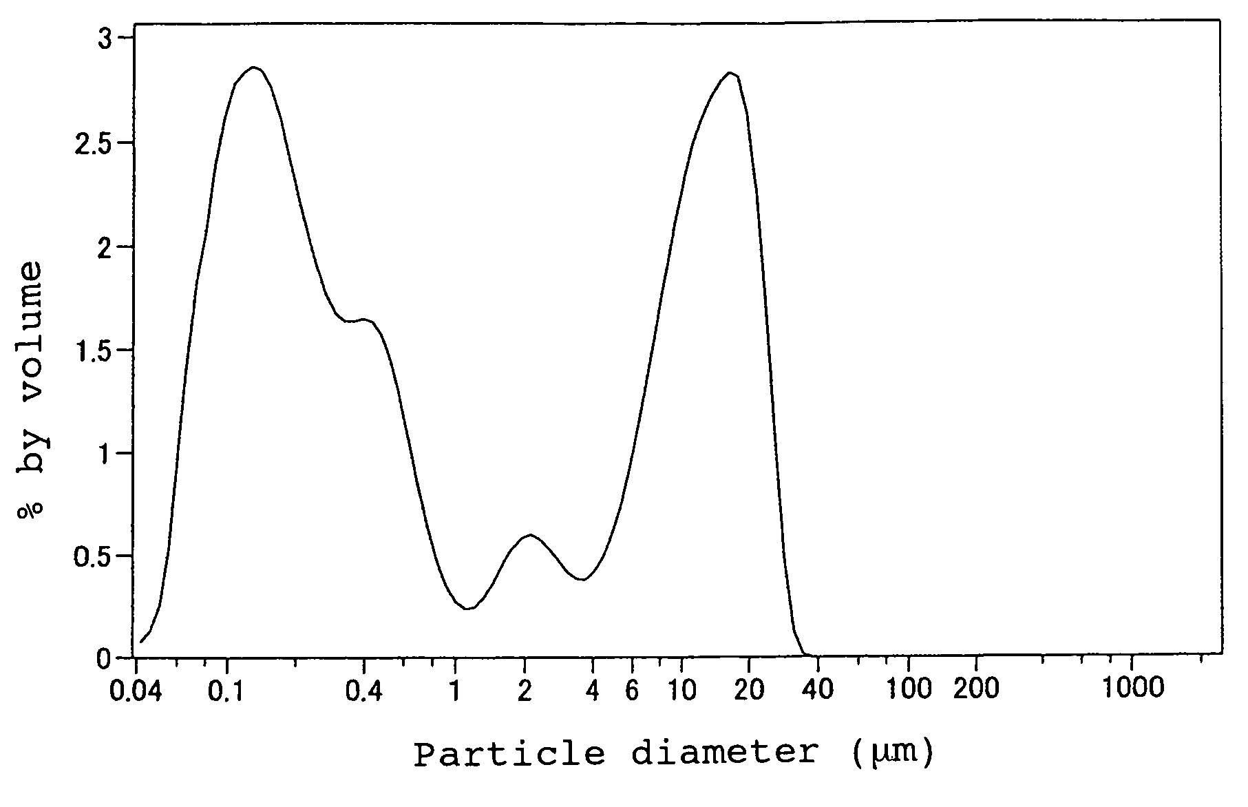
The present invention provides a silica fine particle capable of preventing a charging member or an image bearing member from being contaminated with toner when the toner contains the particle and also capable of providing the toner with a stable developing property. The silica fine particle of the present invention has been hydrophobic treated. Furthermore, the particle has a peak in a range of 0.04 μm to 1 μm and a peak in the range of 1 μm to 100 μm in a volume-basis particle diameter distribution. The particle has a frequency ratio of 10 to 80% for the particles with a particle diameter of 0.04 μm to 1 μm to a total of all the peaks, and the particles has the frequency ratio of less than 16% for the particles with a particle diameters of 20 μm to 2000 μm to the total of all the peaks.

Description

BACKGROUND OF THE INVENTION[0001]1. Field of the Invention[0002]The present invention relates to a silica fine particle, toner, two-component developer and image forming method using the toner all of which can be suitably used to form and develop an electric latent image in electrophotography, static printing or toner jet method.[0003]2. Description of the Related Art[0004]A large number of methods have conventionally been known as electrophotography. In general, an electrostatically charged latent image is formed on a photosensitive member using a photoconductive substance by various units, the latent image is developed with a toner to form a toner image, and the toner image is transferred to a transfer material such as paper as required and is fixed on the transfer material by heat, pressure, both of them, or the like to obtain a copy or printed matter. Residual toner particles remaining on the photosensitive member without being transferred to the transfer material are removed fr...

Claims


Application Information

Patent Timeline
IPC IPC(8): G03G9/08C09C1/30G03G9/087
CPCG03G9/08797G03G9/08755G03G9/08782G03G9/08795C09C1/3081C01P2004/51C01P2004/62C01P2006/12
Inventor YACHI, SHINYAMIKURIYA, YUSHINONAKA, KATSUYUKIWATANABE, SHUNTARO
Owner CANON KK
Learn More