
Image processing apparatus and method of generating color mapping parameters

a color mapping and image processing technology, applied in the field of image processing methods and apparatuses, can solve the problems of time-consuming trial and error in adjusting the color mapping parameters by this method, and it is not in general possible, easy to intuit the effect of a change in these numerical values on the colors printed by the output system, and achieve the effect of accurate matching of colors between an input system and an output system

Inactive Publication Date: 2006-03-21
OKI ELECTRIC IND CO LTD
View PDF7 Cites 19 Cited by
  • Summary
  • Abstract
  • Description
  • Claims
  • Application Information

AI Technical Summary

Benefits of technology

[0008]An object of the present invention is to provide an image processing apparatus and method in which accurate matching of colors between an input system and an output system can be easily attained.
[0012]In either case, the input value can be obtained by having a human operator select, from the reference color pattern, a hue most closely matching the hue of the adjustment color. For the human operator, this is a simple procedure by which accurate color matching results can be obtained without the need for trial and error.

Problems solved by technology

Ideally, all output colors should exactly match the corresponding input colors, but because of the different gamuts of reproducible colors, this is not in general possible.
It is not easy, however, to intuit the effect of a change in these numerical values on the colors printed by the output system.
Even an experienced operator finds adjusting the color mapping parameters by this method a time-consuming process of trial and error, requiring much test printing and comparison of sample images.
Accurate matching of colors between the input and output systems by this method is quite difficult.
Manipulating slide-bars may be more intuitive than entering numerical values, but it is still difficult to visualize what the effect of a slide-bar adjustment will be on the output colors, so the operator must still proceed by trial and error, and accurate color matching remains difficult.

Method used


Image

  • Image processing apparatus and method of generating color mapping parameters
  • Image processing apparatus and method of generating color mapping parameters
  • Image processing apparatus and method of generating color mapping parameters

Examples


first embodiment

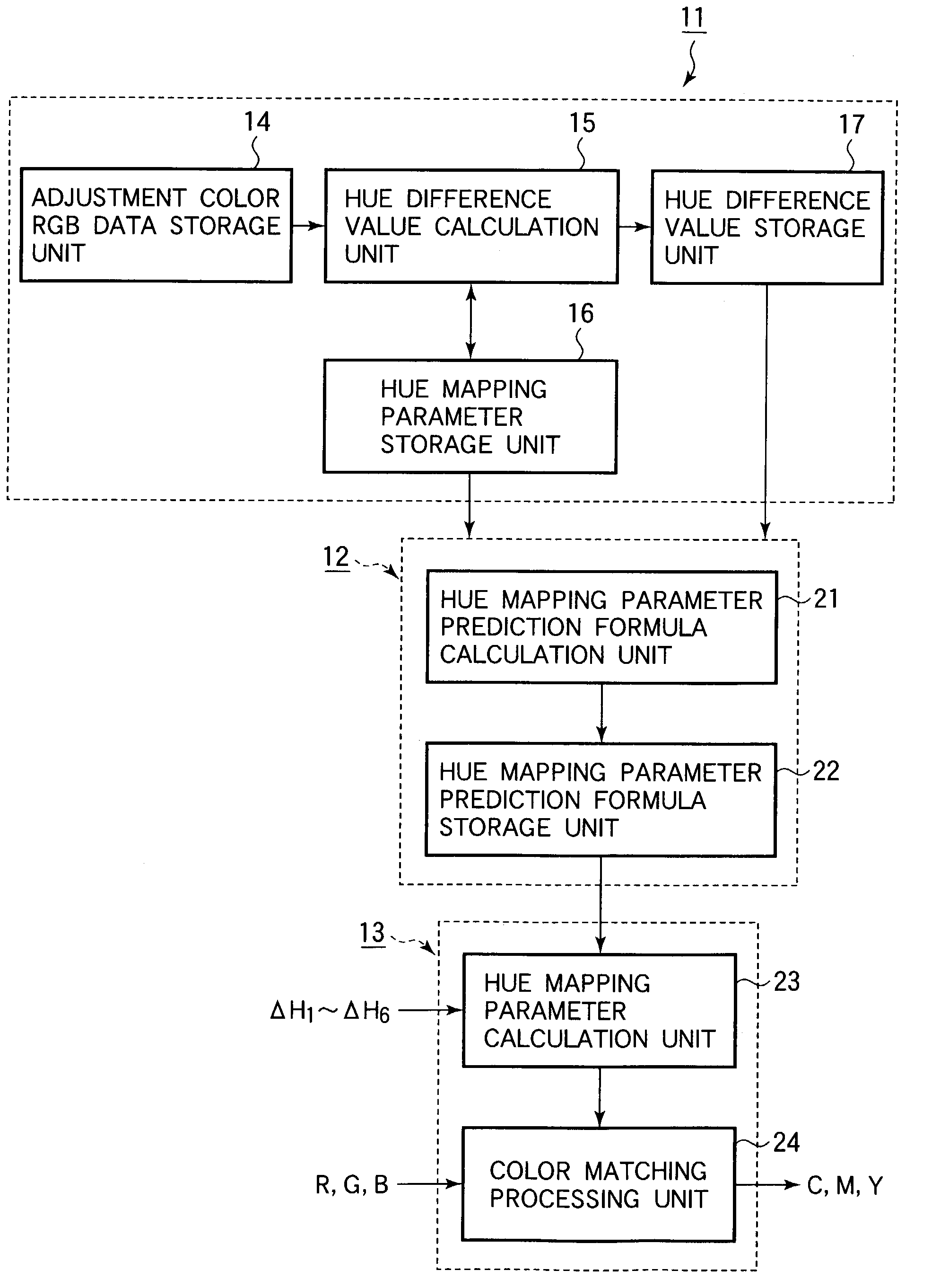
[0026]Referring to FIG. 1, the invention is an image processing apparatus comprising a preprocessing unit 11, a prediction formula calculation unit 12, and a matching processing unit 13. These units 11, 12, 13 collectively include various hardware and software facilities, at least some of which reside in a host computing device connected to a color printer. The host computing device may be, for example, a personal computer; the color printer may be, for example, an electrophotographic printer or an ink-jet printer. The host computing device is also connected to a display unit such as a CRT monitor. From the standpoint of color conversion, the display unit is the input system and the color printer is the output system.

[0027]The preprocessing unit 11 includes an adjustment color RGB data storage unit 14 that stores red-green-blue data for six preset colors referred to below as adjustment colors. The stored data will be denoted Ri, Gi, Bi (i=1, 2, . . . , 6). The six adjustment colors ...

third embodiment

[0039]Various input processing schemes are possible. One example will be shown in the

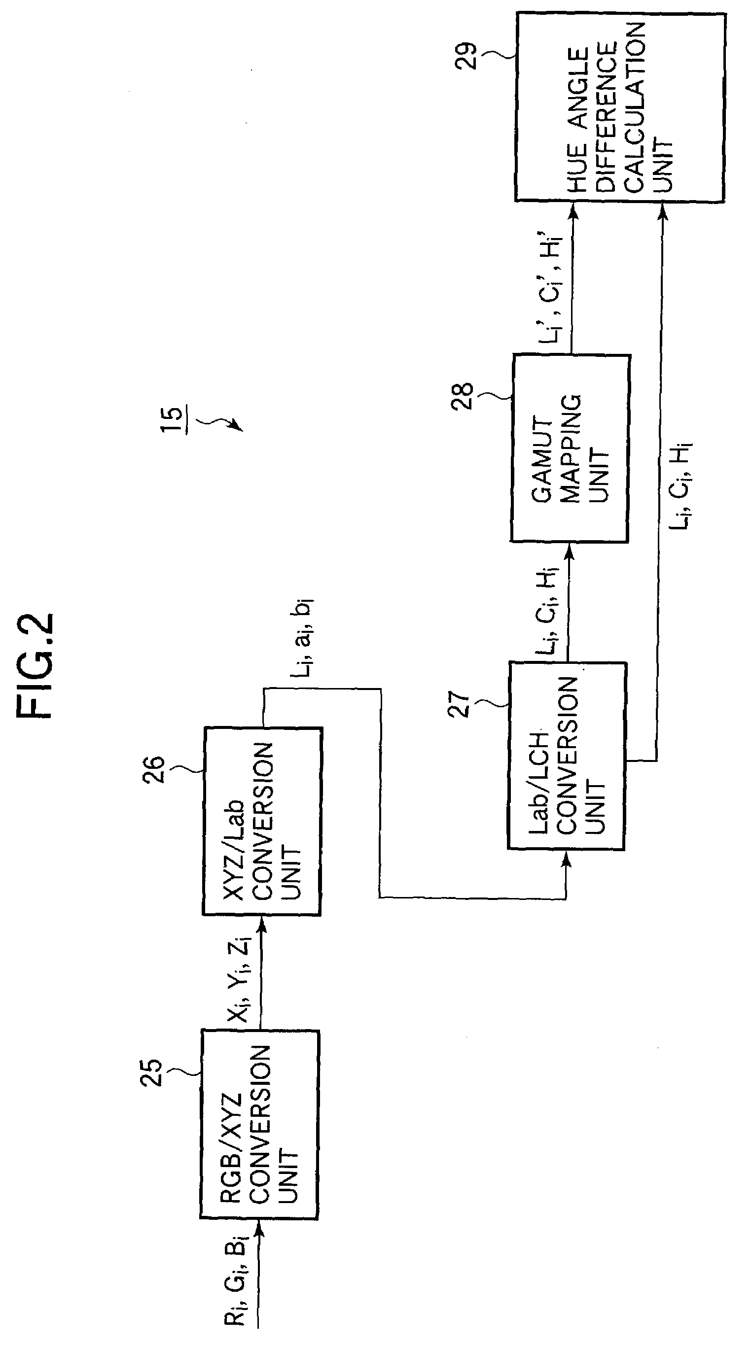
[0040]Next, the internal structure of the hue difference value calculation unit 15 will be described.

[0041]Referring to FIG. 2, the hue difference value calculation unit 15 includes three conversion units. An RGB / XYZ conversion unit 25 maps the RGB values (Ri, Gi, Bi) of the adjustment colors into the CIE XYZ color space and generates their XYZ values (Xi, Yi, Zi) (i=1, 2, . . . , 6). An XYZ / Lab conversion unit 26 maps the XYZ values from the CIE XYZ space to the CIE L*a*b* space and generates corresponding Lab values (Li, ai, bi) (i=1, 2, . . . , 6). The hues HR, HY, HG, HC, HB, HM of red, yellow, green, cyan, blue, and magenta in the input-system gamut are expressed on the a*b* plane in this color space as shown in FIG. 3. A Lab / LCH conversion unit 27 maps the Lab values (Li, ai, bi) from the CIE L*a*b* color space to the LCH color space and generates corresponding LCH values (Li, Ci, Hi) (i=1, 2,...

second embodiment

[0110]Next, the invention will be described.

[0111]FIG. 6 shows a block diagram of an image processing apparatus according to the second embodiment, FIG. 7 shows an example of the reference color pattern printed in the second embodiment, and FIG. 8 shows an example of the printing color adjustment image displayed in the second embodiment.

[0112]The color printer 51 used as the output system in the second embodiment is driven by a printer driver 52 residing as software in the host computing device (not shown). The color printer 51 includes a color matching processing unit 24 as described in the first embodiment, an adjustment color sample data storage unit 53, a printing control unit 54, and a hue mapping parameter storage unit 55. The adjustment color sample data storage unit 53 stores data for printing a reference color pattern in which the mixing ratios of the color components of the adjustment colors are varied in steps. The adjustment colors are the same as in the first embodiment...


PUM


Abstract

Parameters for mapping colors from an input system to an output system are determined by displaying a set of adjustment colors in the input system and outputting a reference color pattern in the output system. A human operator selects the reference colors most closely matching the adjustment colors. The mapping parameters are determined from the operator's selections, by table look-up or by use of a mathematical formula, for example. Accurate color mapping parameters can be generated in this way without the need for trial and error.

Description

BACKGROUND OF THE INVENTION[0001]1. Field of the Invention[0002]The present invention relates to an image processing method and apparatus, and more particularly to a method of selecting color mapping parameters.[0003]2. Description of the Related Art[0004]Conventional color image processing apparatus includes apparatus in which an image displayed by an input system, such as a cathode-ray-tube (CRT) monitor attached to a host computing device, is reproduced by an output system such as an electrophotographic printer or ink-jet printer. Such apparatus typically includes a printer driver, running as software on the host computing device, that can display images on the input system, as well as having images printed by the output system.[0005]In this type of apparatus, the input system displays color images by additive color mixing of three primary colors, normally red, green, and blue (RGB), while the output system prints the same color images by subtractive color mixing of three or four...

Claims


Application Information

Patent Timeline
IPC IPC(8): G09G5/02B41J2/525G06T1/00H04N1/46H04N1/60
CPCH04N1/6075H04N1/6033
Inventor MATSUSHIRO, NOBUHITOKOBAYASHI, YASUSHI
Owner OKI ELECTRIC IND CO LTD
Features
  • Generate Ideas
  • Intellectual Property
  • Life Sciences
  • Materials
  • Tech Scout
  • Unparalleled Data Quality
  • Higher Quality Content
  • 60% Fewer Hallucinations
Learn More