Signal extraction method and apparatus in wireless communication system

Inactive Publication Date: 2006-03-21
NTT DOCOMO INC
View PDF3 Cites 8 Cited by
  • Summary
  • Abstract
  • Description
  • Claims
  • Application Information

AI Technical Summary

Benefits of technology

[0078]According to the signal extraction apparatus, since the dimension extension algorithm which allows high speed convergence is used for estimation and update of weight c

Problems solved by technology

Therefore, the size of the apparatus becomes large.
However, the other route interference canceling apparatus and the side lobe canceler can not be applied to a system such as a mobile wireless communication in which the desired wave direction and the interference wave direction change speedily.
However, as mentioned above, since the adaptive array antennas separate the desired wave and the interference wave by controlling directivity, interference can not be suppressed sufficiently when the desired wave and the interference wave enter the antenna from adjacent directions.
However, when the interval of the elements is widened, interference wave increases so that diversity gain decreases.
In addition, when high-speed signal transmission is performed by using CDMA (Code Division Multiple Access), it can be estimated that delay waves of more than several nu

Method used


Image

  • Signal extraction method and apparatus in wireless communication system
  • Signal extraction method and apparatus in wireless communication system
  • Signal extraction method and apparatus in wireless communication system

Examples


first embodiment

[0098]The signal extraction apparatus 400 is configured as shown in FIG. 6 for example. FIG. 6 shows the present invention.

[0099]In FIG. 6, the signal extraction apparatus 400 includes an input terminal 112 which receives signals from every element of the array antenna, beam forming networks (which will be called as BFN) 113–115 and antenna output terminals 116–118.

[0100]In the following, the operation of the signal extraction apparatus 400 will be described with reference to FIG. 6 and a flowchart in FIG. 7.

[0101]In the signal extraction apparatus 400, first, received signals received by every element of the array antenna are input to each BFN 113–115 (step 100). When the first BFN(1) 113 receives the received signals, the first BFN(1) 113 assigns weights to the received signals and adds weighted received signals so that a signal d1 is extracted, and outputs the signal d1 to the second BFN(2) 114 (step 101).

[0102]In the second BFN(2) 114, the second BFN(2) 114 assigns weights to th...

second embodiment

[0104]The above-mentioned signal extraction apparatus 400 can be configured as shown in FIG. 8 as a

[0105]In FIG. 8, the signal extraction apparatus 400 includes an input terminal 119 which receives signals from all array antennas, an SINR estimation part 120 which estimates SINR of a signal output from each SINR, BFN(1) 121–BFN(K) 124, a matrix switch circuit 125, antenna output terminals 126–128.

[0106]Each of the BFN(1) 121–BFN(K) 124 synthesizes signals received by each array antenna weight assigning weight to each of the signals and add the weighted signals, so as to extract a signal α1, β1, . . . , χK which is the desired wave or the interference wave.

[0107]The SINR estimation part 120 estimates SINR of output of each BFN 121–124, judges from which BNF signal should be extracted first, and generates estimation information for sorting the BFNs in descending order of SINR. In addition, the SINR estimation part 120 outputs the estimation information to each BFN 121–124 and the matr...

third embodiment

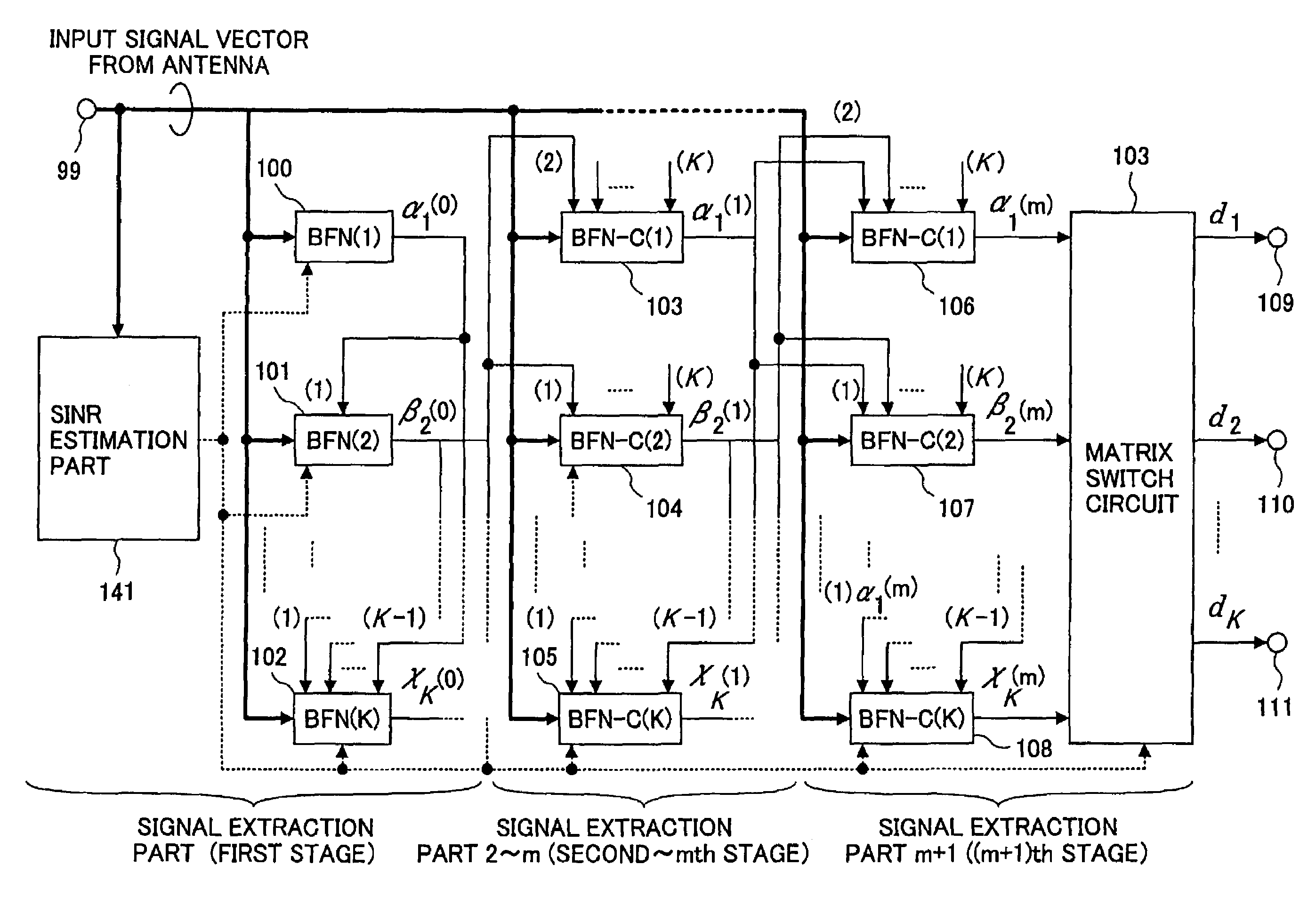
[0156]In addition, the signal extraction apparatus 400 can be configured as shown in FIG. 13 which shows a

[0157]As shown in FIG. 13, the signal extraction apparatus 400 includes an input terminal 99 which receives signals from all elements of the array antenna, an SINR estimation part141 which estimates SINR of each output signal, BFNs 100–108, a matrix switch circuit 142, and output terminals 109–111. The BFNs 100–102 correspond to a first stage signal extraction part 1, the BFNs 103–105 correspond to signal extraction parts after the second stage (from second to mth stage), the BFNs 106˜108 corresponds to the final stage (m+1)th stage.

[0158]In the following, the operation of the signal extraction apparatus 400 will be described with reference to FIG. 13 and a flowchart (FIG. 14).

[0159]The signal extraction apparatus 400 extracts signals β2(0)−χK(0) by performing the same process as the signal extraction apparatus shown in FIG. 8 (step 201). The extracted signals β2(0)−χK(0) are in...


PUM


Abstract

A signal extraction method is provided. In the method, signals are extracted by using K beam forming parts, wherein K is a natural number equal to or more than 2, and received signals from a plurality of antennas are applied to each beam forming part. The method includes the steps of: the received signals being processed by each beam forming part successively; a first beam forming part extracting a first signal from the received signals; and a kth beam forming part canceling, from the received signals, signal components which are extracted by beam forming parts from the first beam forming part to a (k−1)th beam forming part so as to extract a kth signal, wherein 2≦k≦K.

Description

BACKGROUND OF THE INVENTION[0001]1. Field of the Invention[0002]The present invention relates to a signal extraction method and apparatus in a wireless communication system. More particularly, the present invention relates to a signal extraction method and apparatus used in an interference canceling apparatus and the like which cancels degradation due to co-channel interference in communication channels.[0003]2. Description of the Related Art[0004]In the wireless communication system, technologies are known in which interference from an adjacent channel or interference from other systems are canceled by using antennas.[0005]For example, “other route interference canceling apparatus” for canceling interference by using two Cassegrain antennas is known as one of the technologies. The other route interference canceling apparatus is configured as shown in FIG. 1.[0006]The other route interference canceling apparatus includes send apparatuses 2 and 4 sending a desired signal (D) and an i...

Claims


Application Information

Patent Timeline
IPC IPC(8): H03D1/04H01Q3/26H01Q25/04H04B7/08H04B7/10H04B7/26
CPCH04B7/086H01Q3/2605
Inventor DENNO, SATOSHI
Owner NTT DOCOMO INC
Why Eureka
Try Eureka