Method for fast, robust, multi-dimensional pattern recognition

a multi-dimensional pattern and robust technology, applied in the field of fast, robust, multi-dimensional pattern recognition, can solve the problems of inability to detect fine variations, inability to reliably classify pixels as objects or background, and severe degradation of accuracy

Inactive Publication Date: 2006-03-21
COGNEX TECH & INVESTMENT
View PDF36 Cites 132 Cited by
  • Summary
  • Abstract
  • Description
  • Claims
  • Application Information

AI Technical Summary

Benefits of technology

[0064]One aspect of the invention is a solution to the problem of coding a method for scanning non-translation degrees of freedom for the purpose of pattern locating. The coding method requires no duplication of code, and allows non-translation degrees of freedom to be added and removed, and to have the nesting order changed, at run time. The

Problems solved by technology

One limitation is that accuracy can be severely degraded if some of the object is missing or occluded, or if unexpected extra features are present.
Another limitation is that the values available for inspection purposes represent coarse features of the object, and cannot be used to detect fine variations.
The most severe limitation, however, is that except under limited and well-controlled conditions there is in general no reliable method for classifying pixels as object or background.
These limitations forced developers to seek other methods for pattern location and inspection.
One limitation, however, is that a binarization threshold is needed, which can be difficult to choose reliably in practice, particularly under conditions of poor signal-to-noise ratio or when illumination intensity or object contrast is subject to variation.
Accuracy is typically limited to about one whole pixel due to the substantial loss of information associated with thresholding.
Even more serious, however, is that binary template matching cannot measure object orientation and size.
Furthermore, accuracy degrades rapidly with small variations in orientation and/or size, and if larger variations are expected the method cannot be used at all.
The situation regarding orientation and size, however, is not much improved.
Another limitation of correlation methods is that in many applications object shading can vary locally and non-linearly across an object, resulting

Method used


Image

  • Method for fast, robust, multi-dimensional pattern recognition
  • Method for fast, robust, multi-dimensional pattern recognition
  • Method for fast, robust, multi-dimensional pattern recognition

Examples


Embodiment Construction

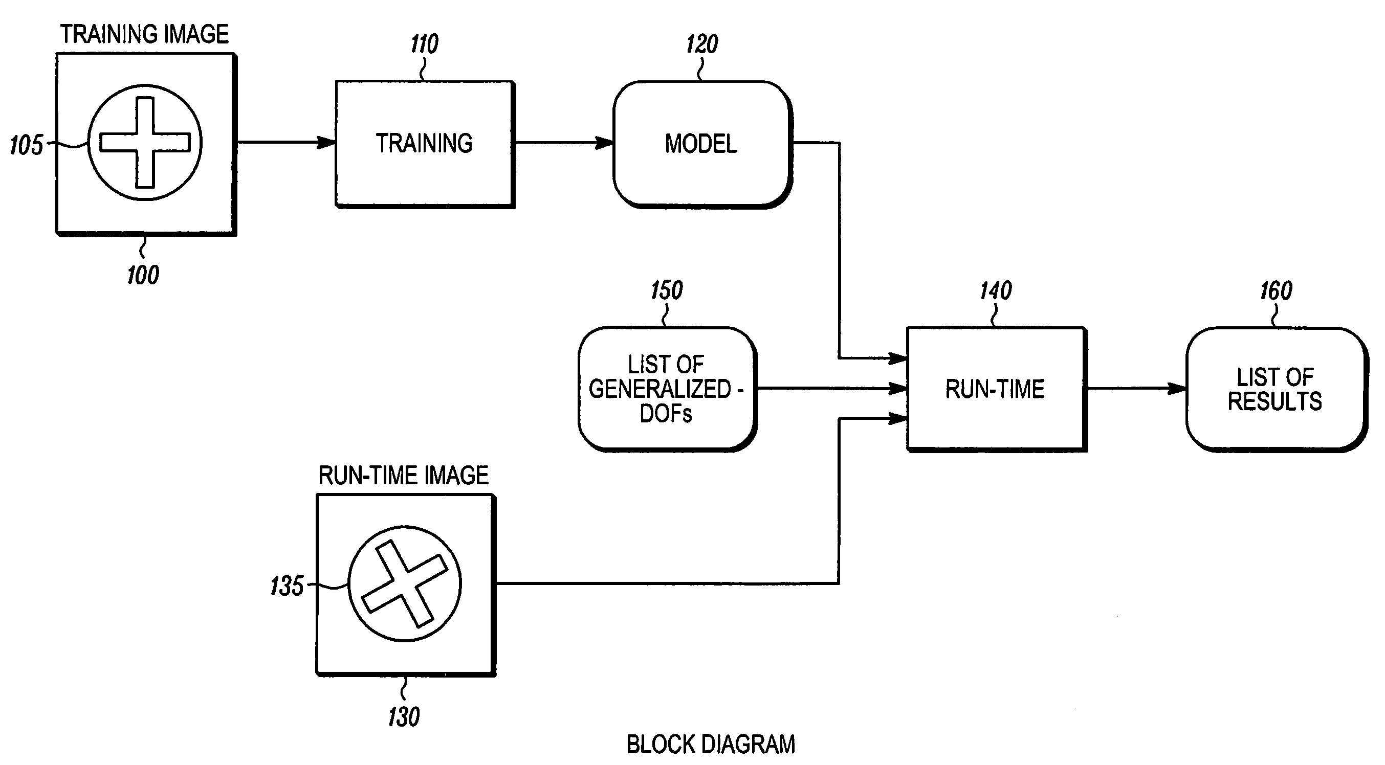
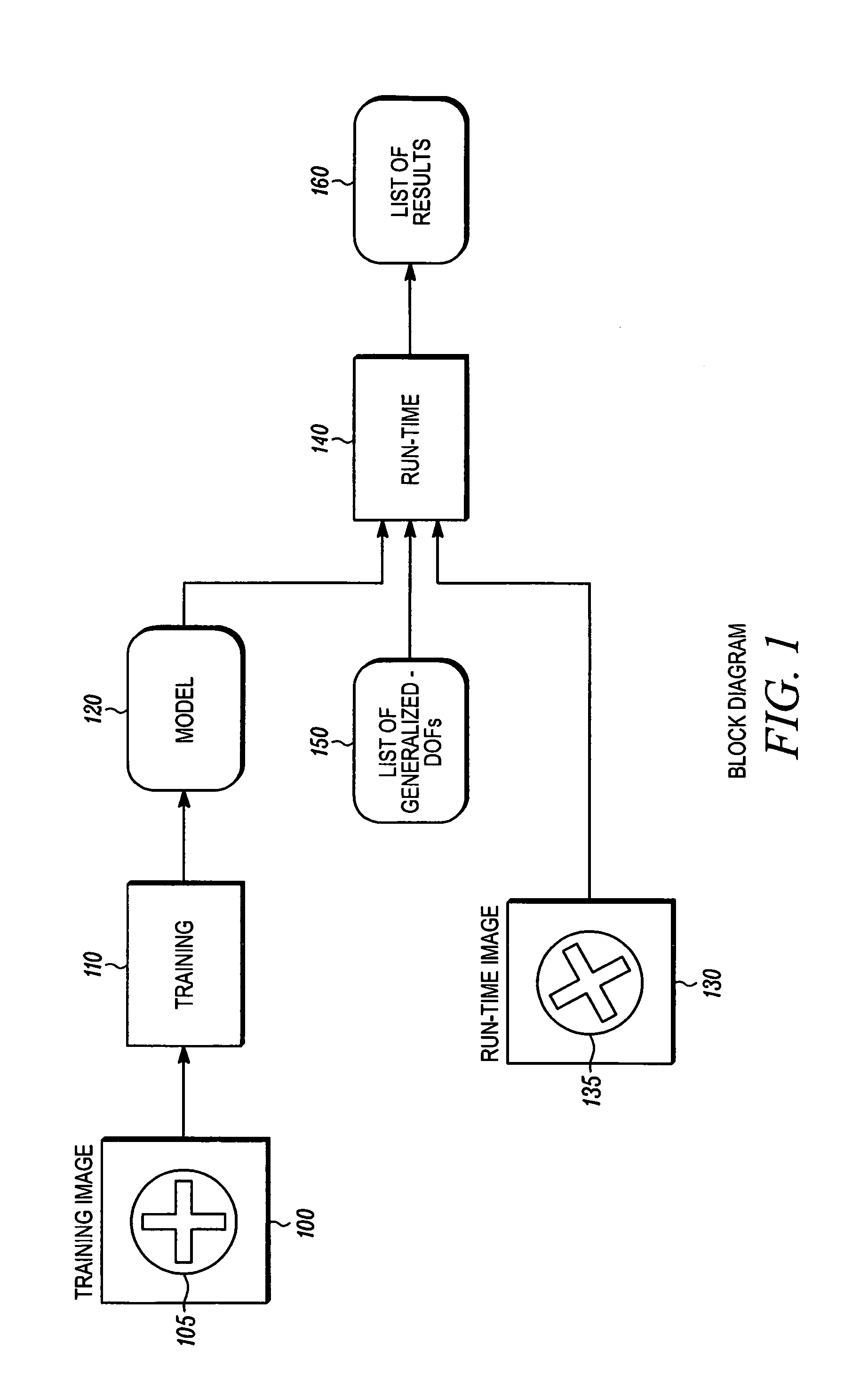
[0110]FIG. 1 is a high-level block diagram of one embodiment of the invention. A training image 100 containing an example of a pattern 105 to be located and / or inspected is presented. A training step 110 analyzes the training image and produces a model 120 for subsequent use. At least one runtime image 130 is presented, each such image containing zero or more instances of patterns 135 similar in shape to the training pattern 105.

[0111]For each run-time image a run-time step 140 analyzes the image 130, using the model 120, and the list of generalized-DOFs 150. As a result of the analysis, the run-time step produces a list 160 of zero or more results, each result corresponding to an instance of the trained pattern 105 in image 130 and containing a pose that maps pattern points to corresponding image points, and individual probe rating information for inspection purposes.

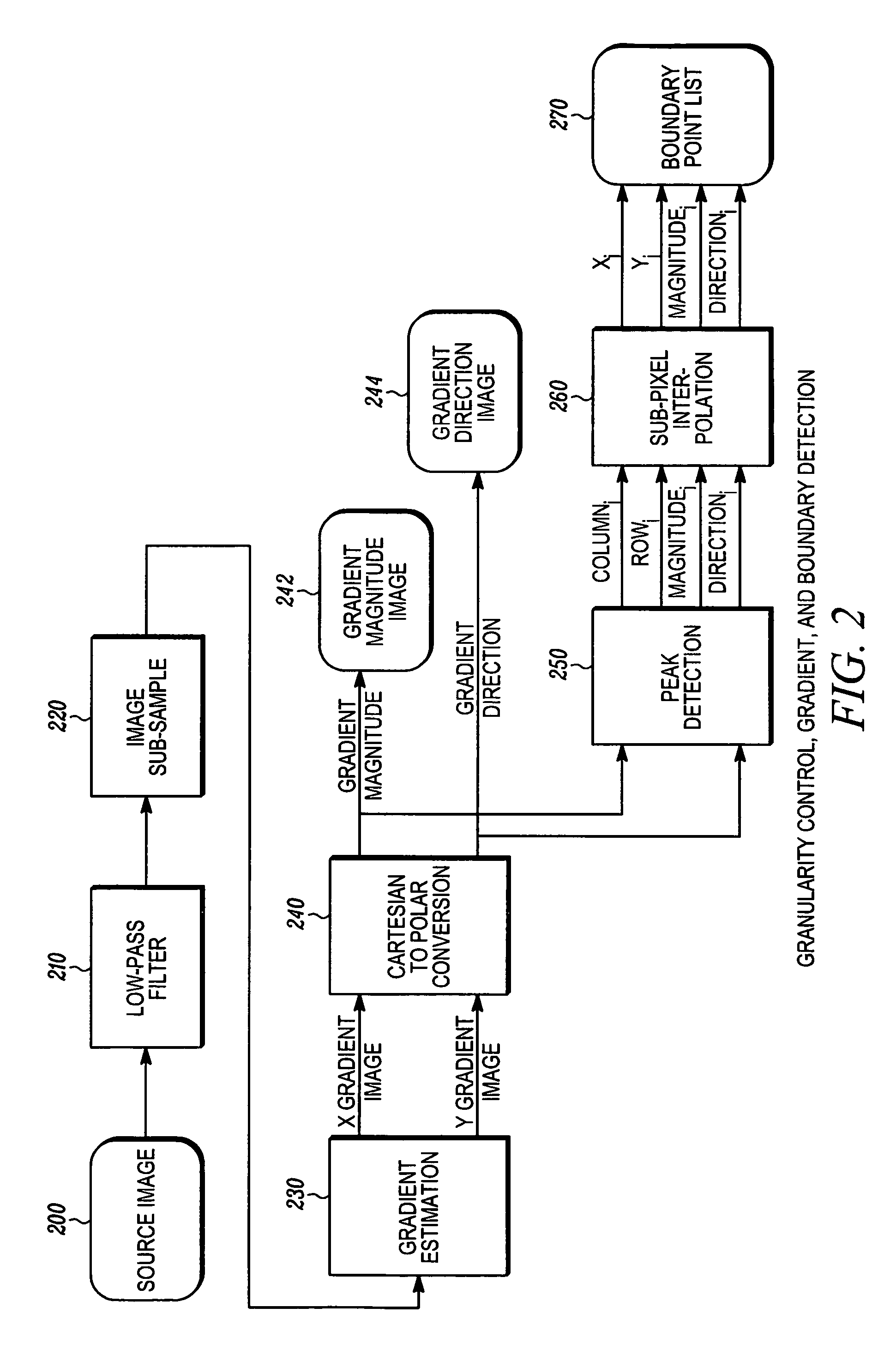
[0112]FIG. 2 shows a preferred embodiment of image processing steps used by the invention during training step 110 a...


PUM


Abstract

Disclosed is a method for determining the absence or presence of one or more instances of a predetermined pattern in an image, and for determining the location of each found instance within a multidimensional space. A model represents the pattern to be found, the model including a plurality of probes. Each probe represents a relative position at which a test is performed in an image at a given pose, each such test contributing evidence that the pattern exists at the pose. The method further includes a comparison of the model with a run-time image at each of a plurality of poses. A match score is computed at each pose to provide a match score surface. Then, the match score is compared with an accept threshold, and used to provide the location any instances of the pattern in the image.

Description

BACKGROUND OF THE INVENTION[0001]Digital images are formed by many devices and used for many practical purposes. Devices include TV cameras operating on visible or infrared light, line-scan sensors, flying spot scanners, electron microscopes, X-ray devices including CT scanners, magnetic resonance imagers, and other devices known to those skilled in the art. Practical applications are found in industrial automation, medical diagnosis, satellite imaging for a variety of military, civilian, and scientific purposes, photographic processing, surveillance and traffic monitoring, document processing, and many others.[0002]To serve these applications the images formed by the various devices are analyzed by digital devices to extract appropriate information. One form of analysis that is of considerable practical importance is determining the position, orientation, and size of patterns in an image that correspond to objects in the field of view of the imaging device. Pattern location methods...

Claims


Application Information

Patent Timeline
IPC IPC(8): G06K9/62G06V30/224
CPCG06K9/481G06K9/6201G06K9/6204G06V10/469G06V10/752G06F18/22
Inventor SILVER, WILLIAM M.MCGARRY, E. JOHNHILL, MATTHEW L.FOSTER, NIGELNICHANI, SANJAYFOSTER, WILLARD P.WAGMAN, ADAM
Owner COGNEX TECH & INVESTMENT
Why Eureka
Try Eureka