

Congestion management in a distributed computer system multiplying current variable injection rate with a constant to set new variable injection rate at source node
a distributed computer system and variable injection technology, applied in the field of communication in distributed computer systems, can solve the problems of congestion of messages communicated over the underlying communication services/fabrics, and congestion in large distributed computer systems is a significant problem today
- Summary
- Abstract
- Description
- Claims
- Application Information
AI Technical Summary
Benefits of technology
Problems solved by technology
Method used
Image

Examples
example request
and Acknowledgment Transactions
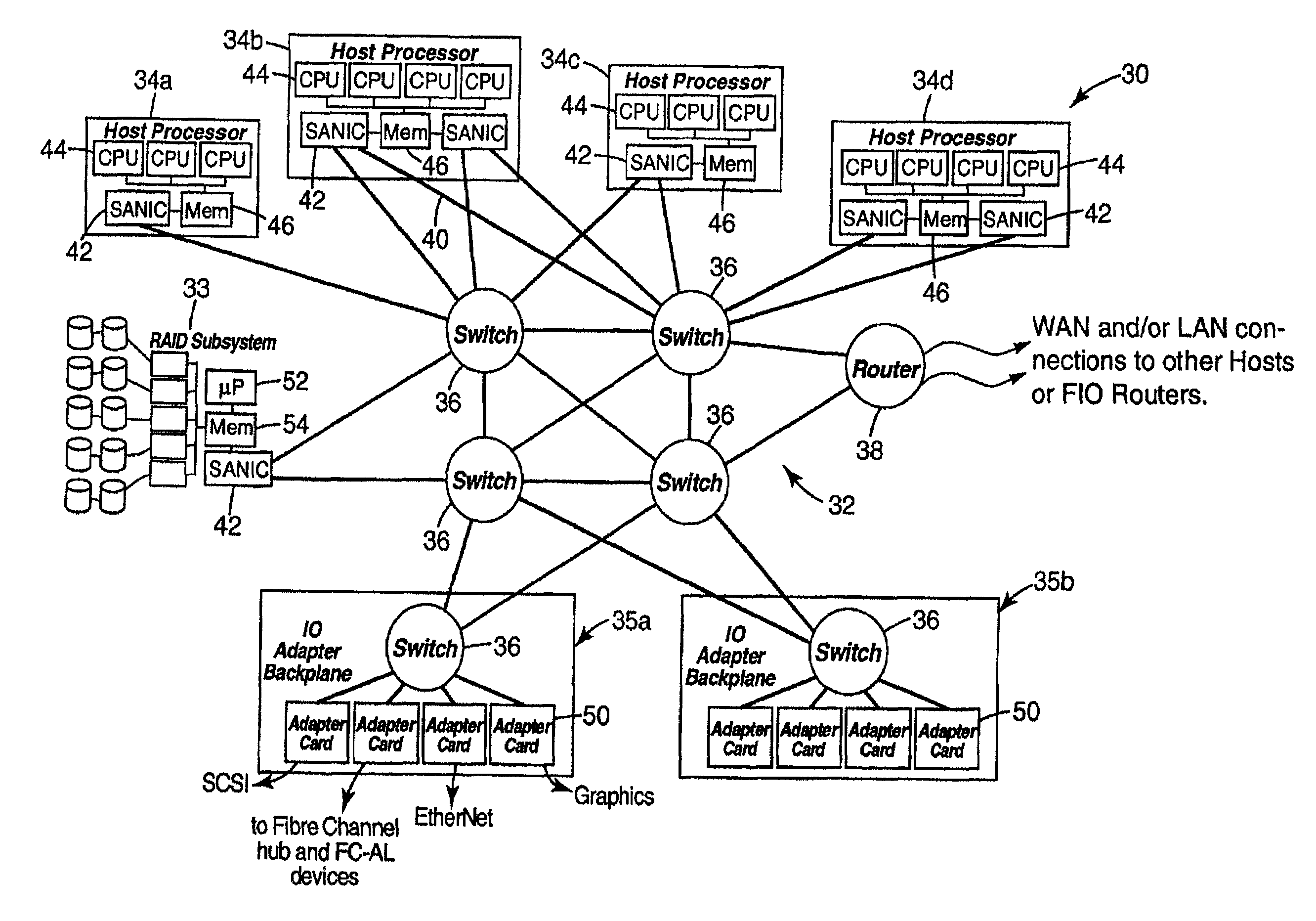
[0100]FIGS. 8, 9A, 9B, 10A, and 10B together illustrate example request and acknowledgment transactions. In FIG. 8, a portion of a distributed computer system is generally illustrated at 300. Distributed computer system 300 includes a host processor node 302 and a host processor node 304. Host processor node 302 includes a SANIC 306. Host processor node 304 includes a SANIC 308. Distributed computer system 300 includes a SAN fabric 309 which includes a switch 310 and a switch 312. SAN fabric 309 includes a link 314 coupling SANIC 306 to switch 310; a link 316 coupling switch 310 to switch 312; and a link 318 coupling SANIC 308 to switch 312.
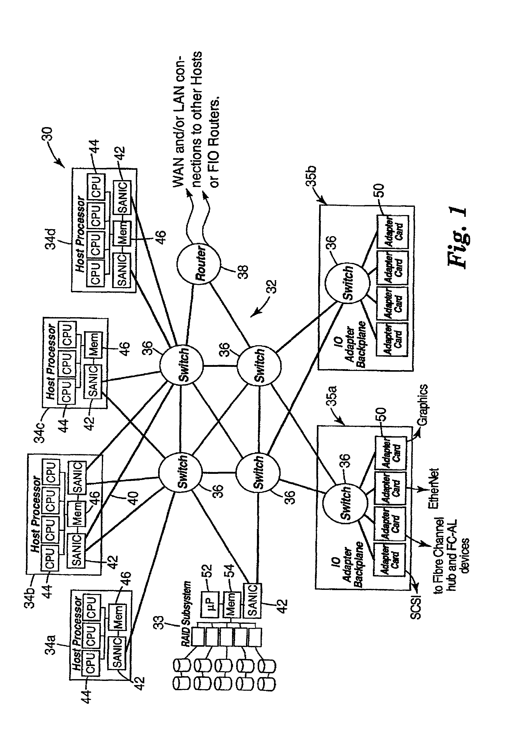
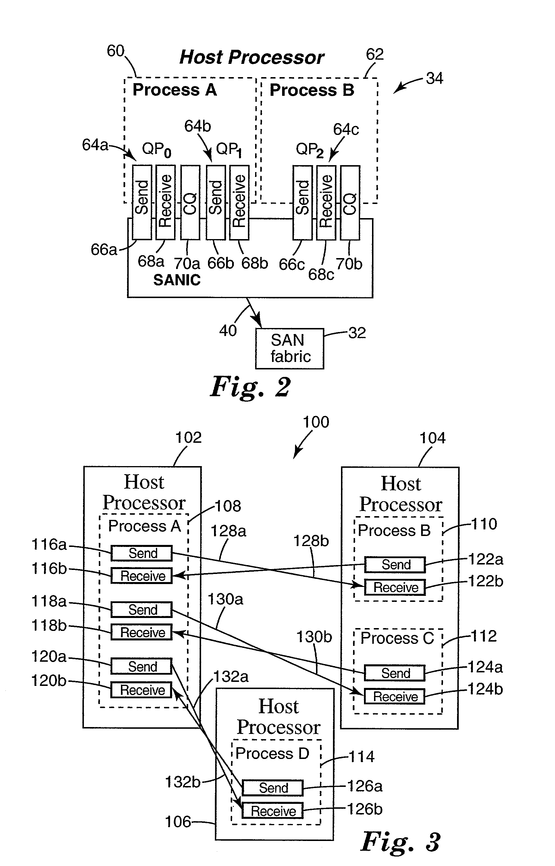
[0101]In the example transactions, host processor node 302 includes a client process A indicated at 320. Host processor node 304 includes a client process B indicated at 322. Client process 320 interacts with SANIC hardware 306 through QP 324. Client process 322 interacts with SANIC hardware 308 through QP 326. QP 3...
example congestion
MANAGEMENT POLICIES
Example 1
No Drops within SAN Fabric, Drops when Non-SAN Fabric Transports Solely Over a SAN Fabric Network
[0184]Link lever back pressure is used. This means there are not any lot frames due to congestion.
[0185]The NormalCongestionTimer=Abnormal Congestion Timer.
[0186]Each QP uses the minimum number of outstanding requests to achieve the desired BW for the necessary distance to the destination. (i.e., once maximum BW is achieved, a larger window size can only increase congestion).
[0187]Each QP should inject frames at no higher than the maximum W of the slowest link in use. This is important if there are multiple speed SAN Fabric links in use.
[0188]The request-response timer should be set high enough that a time-out implies a frame is lost due to an error (as opposed to congestion).
Legacy Protocols Solely over an SAN Fabric network.
[0189]Legacy protocol (e.g. TCP) are sent as Raw Datagram frames. These frames do not have an SAN Fabric acknowledgment frame. All ackno...
example 2
Drop Datagram and Raw Frame Under Normal Congestion within SAN Fabric, Drops when Non-SAN Fabric Transports Solely Over a SAN Fabric Network
[0200]Link level back pressure is used. This means there aren't any lost frames due to congestion.
[0201]NormalCongestionTimer is set to 1 / Nth the value of the AbnormalCongestionTimer.
[0202]All of the normal congestion detection, reporting and response mechanisms are implemented, summarized below for completeness:
[0203]Detection:[0204]Switch—Detects congestion by analyzing receive and send port resources as stated earlier.[0205]Source—Detects congestion reported by analyzing the FECNCount field in the frame transport header as stated earlier.[0206]Destination—Detects congestion reported by analyzing the FECNCount field in the frame transport header as stated earlier.
[0207]Reporting:[0208]Switch—Propagates the FECNCount field in the flit delimiters as stated earlier.[0209]Routers—When a flit has non-zero FECNCount field, sends a No-Op frame to the...
PUM
 Abstract
Description
Claims
Application Information