Pneumatic cocking device

Inactive Publication Date: 2006-03-28
SMITH DOUGLAS LANE
View PDF7 Cites 51 Cited by
  • Summary
  • Abstract
  • Description
  • Claims
  • Application Information

AI Technical Summary

Benefits of technology

[0024]Also in the preferred embodiment, a side bolt or lever arm protruding out of the crossbow for hand actuation is used to manually move the pick up arm assembly without the need to use compressed gas. The archer manually draws the string pick arm to the bowstring and releases the bowstring with the firing mechanism. There is no need for the archer to grab the side bolt upon un-cocking because the displaced piston volume escaping as the bow limbs pull on the mechanism is restricted, reta

Problems solved by technology

If an archer has a less than healthy back or simply limited physical strength, it may be impossible for one to draw the bowstring.
If an archer is using a tree stand, it may be very challenging, thus unsafe to draw a bowstring on such a tiny platform.
Adverse weather conditions such as severe wet and cold conditions dictate that the archer use heavy gloves as well as the equipment being potentially wet or icy introduce further challenges.
Additionally, in severe cold conditions, it may be nearly impossible to draw the string with cold or gloved fingers or grasp the ropes in ones hands that attach to the hooks for drawing.
Even if environmental conditions are excellent and the archer is in adequate physical shape, it takes time to set up such cocking mechanisms and then adequately stow such systems when not in use.
In the event that the archer slips while using such a device, a goat's foot can be potentially dangerous.
The models with low mech

Method used


Image

  • Pneumatic cocking device
  • Pneumatic cocking device
  • Pneumatic cocking device

Examples


Embodiment Construction

[0029]In the following detailed description of preferred embodiments of the present invention, reference is made to the accompanying drawings that, in conjunction with this detailed description, illustrate a crossbow cocking and un-cocking mechanism.

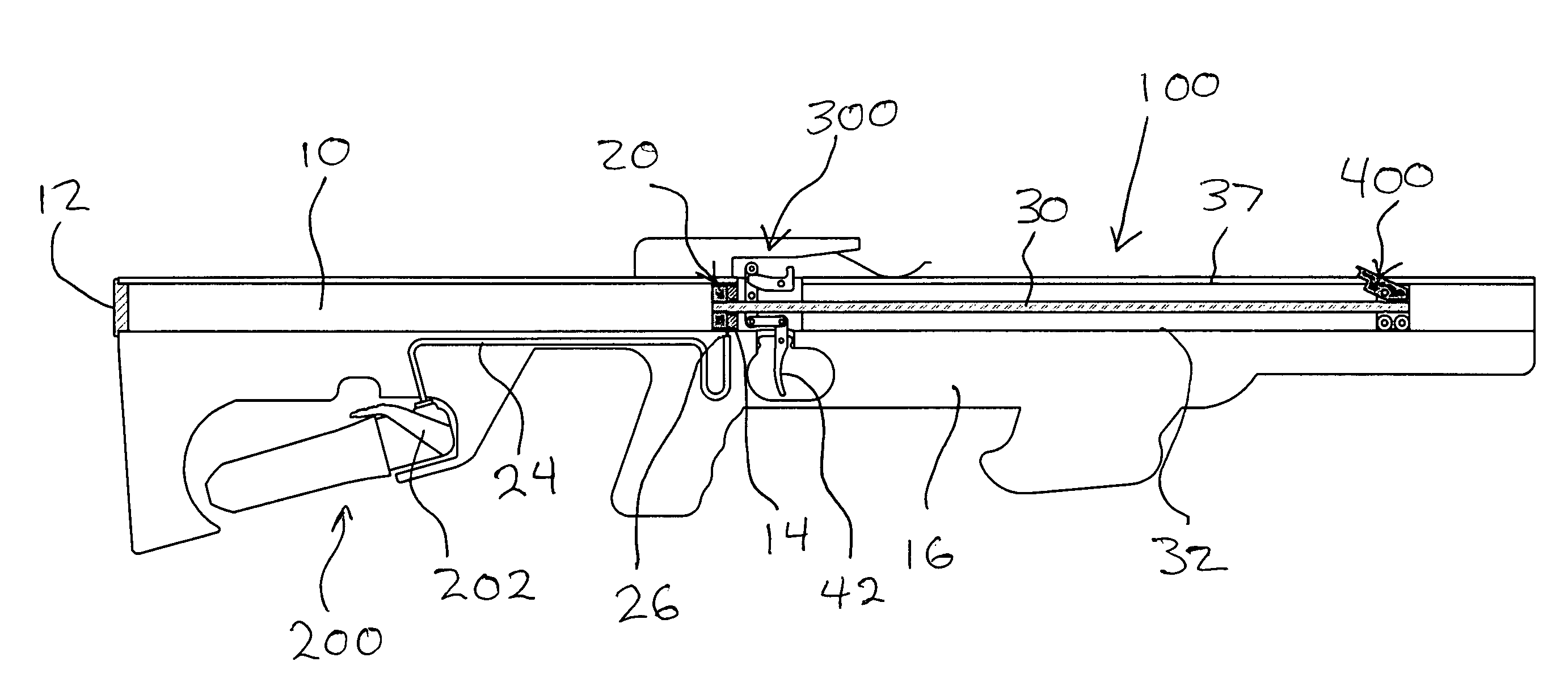
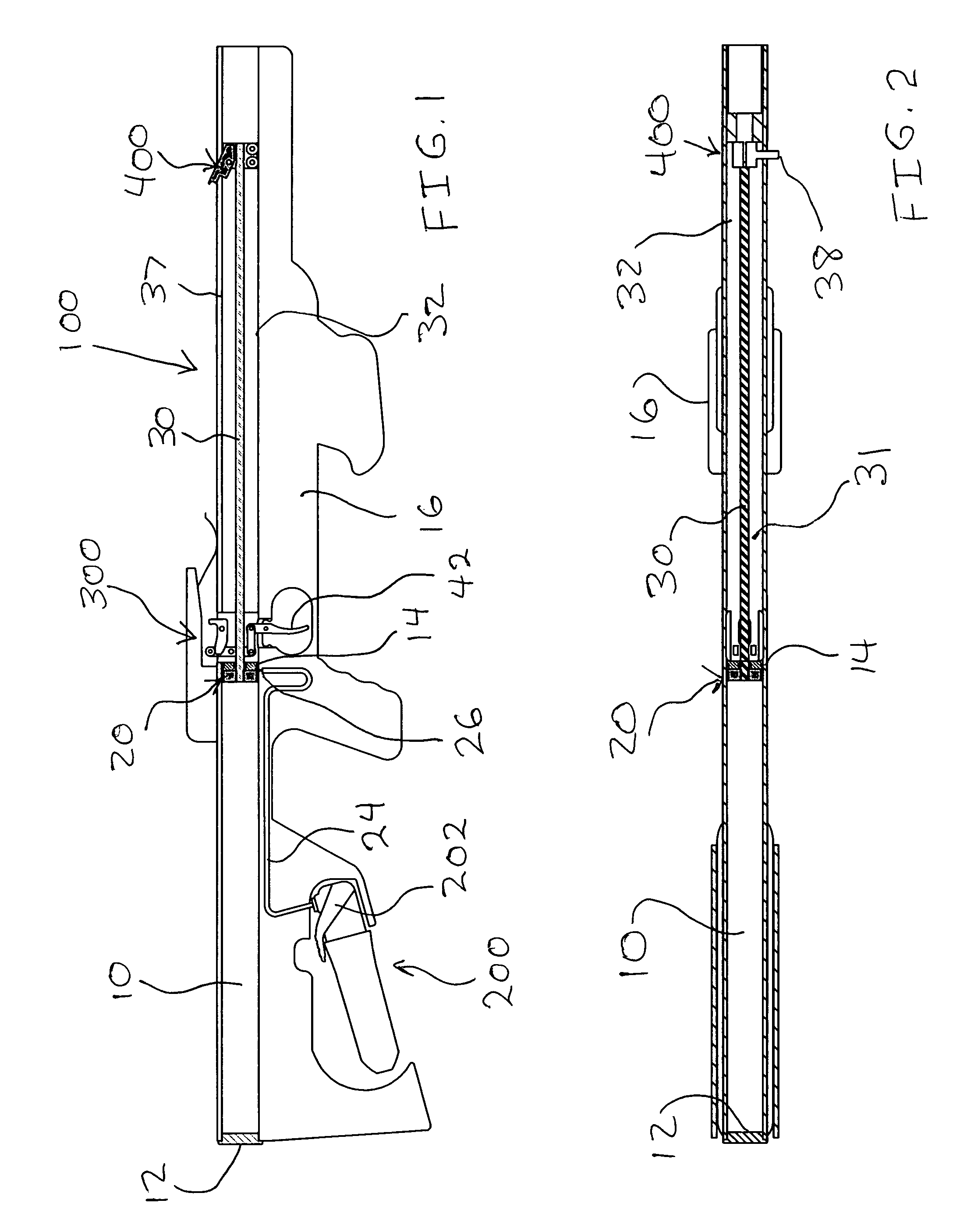
[0030]Referring now to the drawings, like-referenced elements indicate corresponding elements throughout the several views or embodiments. Attention is first directed to FIG. 1 which illustrates the preferred embodiment, in-line pneumatically-actuated crossbow 100 shown in a complete side sectional view. For illustration simplification purposes, the bow limbs and bowstring have been omitted from this and all figures.

[0031]FIG. 1, showing the complete invention, preferably orients the pneumatic cylinder 10, piston assembly 20, connecting rod 30, and operatively connected pick up arm assembly 400 all in an in-line layout.

[0032]Pneumatic cylinder 10 is preferably mounted in the crossbow stock 16 and completely housed, thus supported by the ...


PUM


Abstract

The present invention relates generally to crossbow bowstring drawing mechanisms, also called cocking mechanisms in the art. More particularly, the present invention relates to a crossbow bowstring drawing mechanism that is integrated into a crossbow. The mechanism primarily consists of a pneumatically actuated piston and cylinder assembly, a compressed gas dispenser, and a string pick up arm. An after-the-fact bolt-on kit is also intended to be within the scope of this application allowing retrofit to existing bows not currently outfitted with this cocking feature. The bowstring cocking mechanism may utilize an internal power source such as compressed carbon dioxide (CO2) cartridge, or a plurality of cartridges to actuate the pneumatics that are part of the cocking mechanism on demand. Such actuation draws a bowstring from the un-cocked position to the cocked position. Likewise, such actuation will equally allow a controlled dry-fire, allowing the bowstring to be released from the cocked position to the un-cocked position; the pneumatics acting as a system damper, preventing damage to the bow limbs.

Description

CROSS REFERENCE TO RELATED APPLICATIONS[0001]Not Applicable.FEDERALLY SPONSORED RESEARCH[0002]Not Applicable.SEQUENCE APPENDAGES[0003]Not Applicable.FIELD OF THE INVENTION[0004]The present invention relates generally to crossbow bowstring drawing mechanisms, also called cocking mechanisms in the art. More particularly, the present invention relates to a crossbow bowstring drawing mechanism that is integrated into a crossbow. An after-the-fact bolt-on kit is also intended to be within the scope of this application allowing retrofit to existing bows not currently outfitted with this cocking feature. The bowstring cocking mechanism may utilize an internal power source such as a compressed carbon dioxide (CO2) cartridge, or a plurality of cartridges to actuate the pneumatics that are part of the cocking mechanism on demand. Such actuation will draw a bowstring from the un-cocked position to the cocked position. Likewise, such actuation will equally allow a controlled dry fire, allowing ...

Claims


Application Information

Patent Timeline
IPC IPC(8): F41B5/12
CPCF41B5/1469F41B5/12
Inventor SMITH, DOUGLAS LANE
Owner SMITH DOUGLAS LANE
Why Eureka
Try Eureka