
Coarse carbide substrate cutting elements and method of forming the same

a technology of coarse carbide substrate and cutting element, which is applied in the direction of drags, mechanical machines/dredgers, applications, etc., can solve the problems and affecting the cutting effect of the cutting element, so as to achieve the effect of shortening the operating life of the cutting element and reducing the cost of production

Inactive Publication Date: 2006-03-28
SMITH INT INC
View PDF53 Cites 109 Cited by
  • Summary
  • Abstract
  • Description
  • Claims
  • Application Information

AI Technical Summary

Benefits of technology

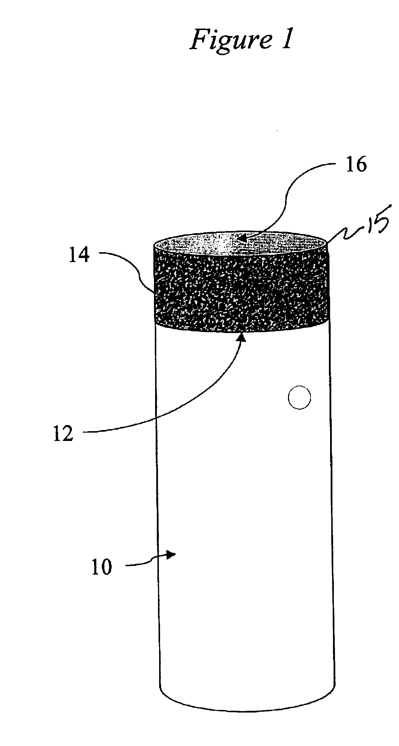
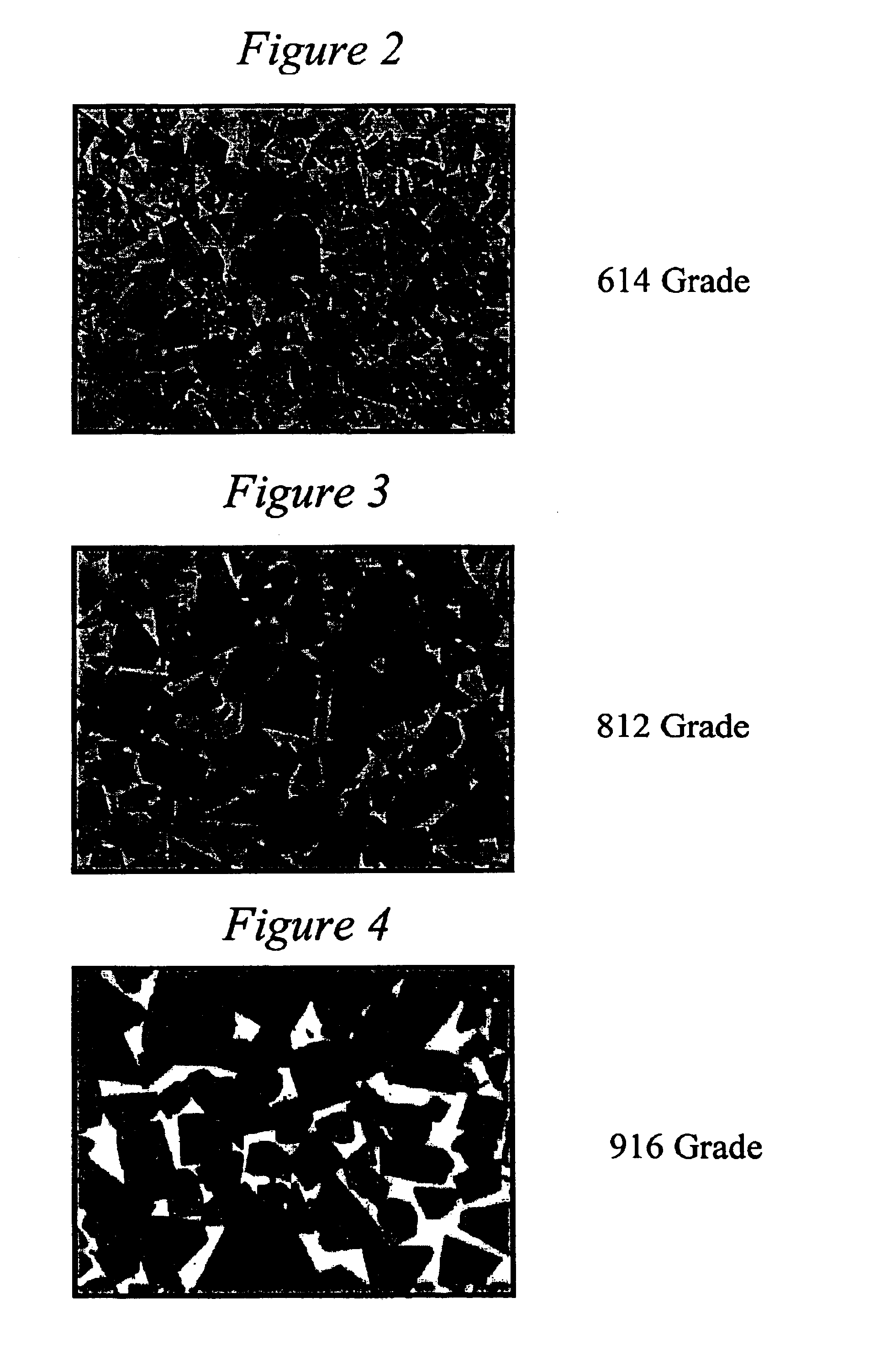
[0022]In another exemplary embodiment, a method is provided for manufacturing a cutting element by providing a substrate having an endsurface. The substrate is formed from a composition including tungsten carbide having a median particle size of at least 6 μm and / or an impurity content of not greater than 0.1% by weight, and a binder material. The substrate is formed by heating the composition causes the binder to infiltrate and cement the tungsten carbide. An ultra hard material layer is placed over the substrate end surface and the resulting assembly of substrate and ultra hard material layer is processed at a sufficient temperature and pressure for forming polycrystalline ultra hard material and metallurgicaly joining of the substrate and polycrystalline ultra hard material. In a further exemplary embodiment method, the tungsten carbide is provided in powder form and is cemented with a binder during the act of heating for forming the polycrystalline ultra hard material. In an alternate exemplary embodiment, the tungsten carbide powder and binder may be heated to at least partly cement the tungsten carbide powder prior to heating for forming the polycrystalline ultra hard material. Other conventional methods may be used for forming the cutting elements of the present invention.
[0023]In another exemplary embodiment method, the tungsten carbide is provided in powder form having a 6% concentration of particles having a grain size of at least 7 μm. In yet a further exemplary embodiment, the binder includes cobalt, and the impurity content of the tungsten carbide powder is controlled to provide a thermal conductivity not less than a value Kmin as determined by the following equation:
[0024]In a further exemplary embodiment method the binder comprises cobalt, and the impurity content of the tungsten carbide powder is controlled to provide a thermal conductivity not less than a value Kmin as determined by the following equation:

Problems solved by technology

Common problems that plague cutting elements having an ultra hard material layer, such as PCD or PCBN bonded on a carbide substrate are chipping, spalling, partial fracturing, cracking or exfoliating of the cutting table.
These problems result in the early failure of the ultra hard layer and thus, in a shorter operating life for the cutting element.
Typically, these problems may be the result of peak (high magnitude) stresses generated on the ultra hard layer at the region in which the layer makes contact with an external body, such as when the cutting layer makes contact with the earthen formation during drilling.
For example, cracks initiated in the ultra hard material layer due to contact loads can propagate into the substrate.
As a result, thermal fatigue and heat checking in tungsten carbide substrates are issues that have not been adequately resolved.
Consequently, substrates made of conventional tungsten carbide grades frequently fail due to heat checking and thermal fatigue when subjected to high temperature and high loads.

Method used


Image

  • Coarse carbide substrate cutting elements and method of forming the same
  • Coarse carbide substrate cutting elements and method of forming the same
  • Coarse carbide substrate cutting elements and method of forming the same

Examples


example 1

[0074]This example shows that a coarse grain grade carbide substrate has an improved thermal conductivity, i.e., higher than Kmin. Thermal conductivity may be measured by various methods conventional in the art. In this example, thermal conductivity is obtained by the flash method in accordance with the American Standard Testing Manual (“ASTM”) standard E 1461-92 for measuring thermal diffusivity of solids. Thermal conductivity is defined as the time rate of steady heat flow through a unit thickness of an infinite slab of a homogeneous material in a direction perpendicular to the surface, induced by a unit temperature difference. Thermal diffusivity of a solid material is equal to the thermal conductivity divided by the product of the density and specific heat. The specific heat of a WC / Co system can be measured by differential scanning calorimetry based on ASTM-E 1269-94 and is generally in the range of about 0.05 cal / gK for conventional carbide grades used in drag bit applications...

example 2

[0077]FIG. 10 provides a comparison of wear resistance data for the coarse grain substrates and conventional substrates. In this Figure the fracture toughness of the materials is plotted versus the wear number of the materials.

[0078]To evaluate the toughness of a carbide, the ASTM B771 test, which measures the fracture toughness (K1c) of cemented tungsten carbide material, was used. It has been found that the ASTM B771 test, correlates well with the insert breakage resistance in the field.

[0079]This test method involves application of an opening load to the mouth of a chevron-shaped slot formed in a short rod or short bar specimen. Load versus displacement across the slot at the specimen mouth is recorded autographically. As the load is increased, a crack initiates at the point of the chevron-shaped slot and slowly advances longitudinally, tending to split the specimen in half. The load goes through a smooth maximum when the width of the crack front is about one-third of the specime...

example 3

[0085]Palmquist toughness, in kg / mm, and hardness, in Ra, were measured and plotted in FIG. 11 for both coarse substrates and conventional carbide substrates. Two groups of specimens were prepared. One group consisted of specimens of the following conventional grades: 510, 512, and 614. The other group consisted of specimens of the following coarse grades: 712, 812, 814, 912, 914, and 916. As shown in FIG. 11, the coarse substrates showed improved Palmqvist toughness when compared to the standard substrate materials.


PUM

PropertyMeasurementUnit
particle sizeaaaaaaaaaa
median particle sizeaaaaaaaaaa
grain sizeaaaaaaaaaa

Abstract

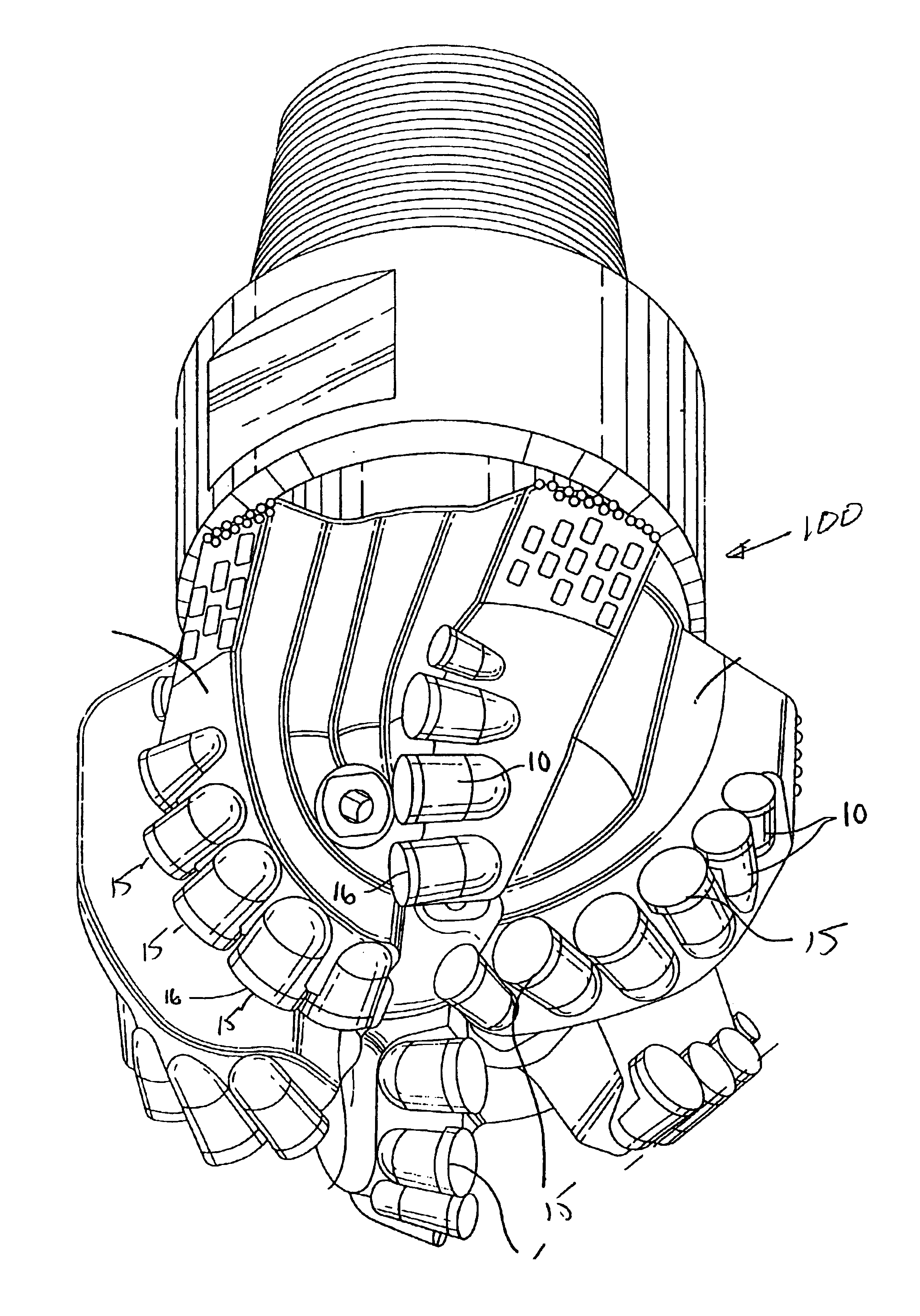
Cutting elements having coarse grain substrates and ultra hard material layers are provided. The substrates are formed from coarse grain size particles of tungsten carbide. A method of forming such cutting elements and a drag bit incorporating such cutting elements are also provided.

Description

CROSS-REFERENCE TO RELATED APPLICATION[0001]This application claims priority based on U.S. provisional application No. 60 / 398,374, filed Jul. 24, 2002, which is incorporated herein by reference.FIELD OF THE INVENTION[0002]The present invention is generally related to a method for forming coarse carbide substrates for cutting elements and more particularly to a high pressure and high temperature synthesis method of forming polycrystalline diamond (“PCD”) and polycrystalline cubic boron nitride (“PCBN”) cutting elements, to such cutting elements and to a drag bit incorporating the same.BACKGROUND OF THE INVENTION[0003]Cutting elements such as shear cutters for drag bit type of rock bits, for example, typically have a body (or substrate), which has a contact face. An ultra hard layer is bonded to the contact face of the body by a sintering process to form a cutting layer (sometimes referred to as a “cutting table”). The body is generally made from tungsten carbide-cobalt (sometimes ref...

Claims


Application Information

Patent Timeline
Patent Type & Authority Patents(United States)
IPC IPC(8): E21B10/08E21B10/46C22C29/08C23C30/00E21B10/56E21B10/567
CPCC22C29/08E21B10/567C23C30/005E21B10/50
Inventor KESHAVAN, MADAPUSI K.GRIFFO, ANTHONYTRUAX, DAVIDLIANG, DAH-BEN
Owner SMITH INT INC
Learn More