Light guide plate for liquid crystal display

a technology of light guide plate and liquid crystal display, which is applied in the direction of lighting and heating apparatus, instruments, mechanical equipment, etc., can solve the problems of unduly complicated assembly procedures, high manufacturing costs, and the limited efficacy of light guide plate b>2/b> in reducing the number of elements in the overall system, and achieves excellent light utilization and uniform luminance. uniformity, low manufacturing costs, and excellent light utilization

Inactive Publication Date: 2006-03-28
HON HAI PRECISION IND CO LTD
View PDF13 Cites 90 Cited by
  • Summary
  • Abstract
  • Description
  • Claims
  • Application Information

AI Technical Summary

Benefits of technology

[0007]Accordingly, an object of the present invention is to provide a light guide plate which is simple, has low manufacturing costs, and has a light emitting surface which provides excellent light utilization and uniformity in luminance.

Problems solved by technology

This results in high manufacturing costs and unduly complicated assembly procedures.
Therefore, the light guide plate 2 has limited efficacy in decreasing the number of elements in the overall system.

Method used


Image

  • Light guide plate for liquid crystal display
  • Light guide plate for liquid crystal display
  • Light guide plate for liquid crystal display

Examples


Embodiment Construction

[0017]Reference will now be made to the drawings to describe the present invention in detail.

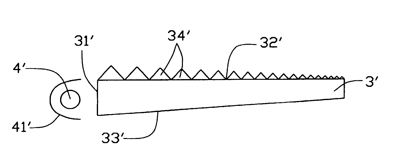
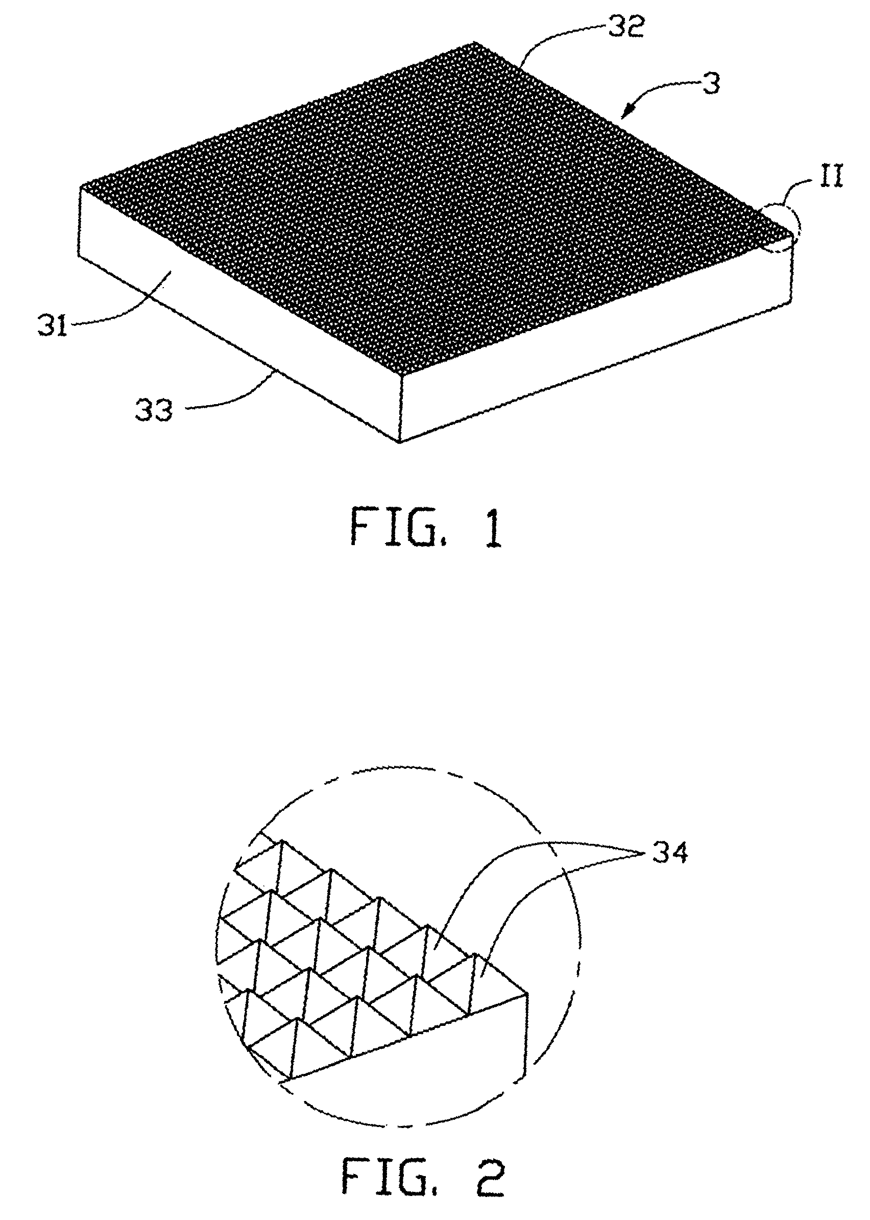
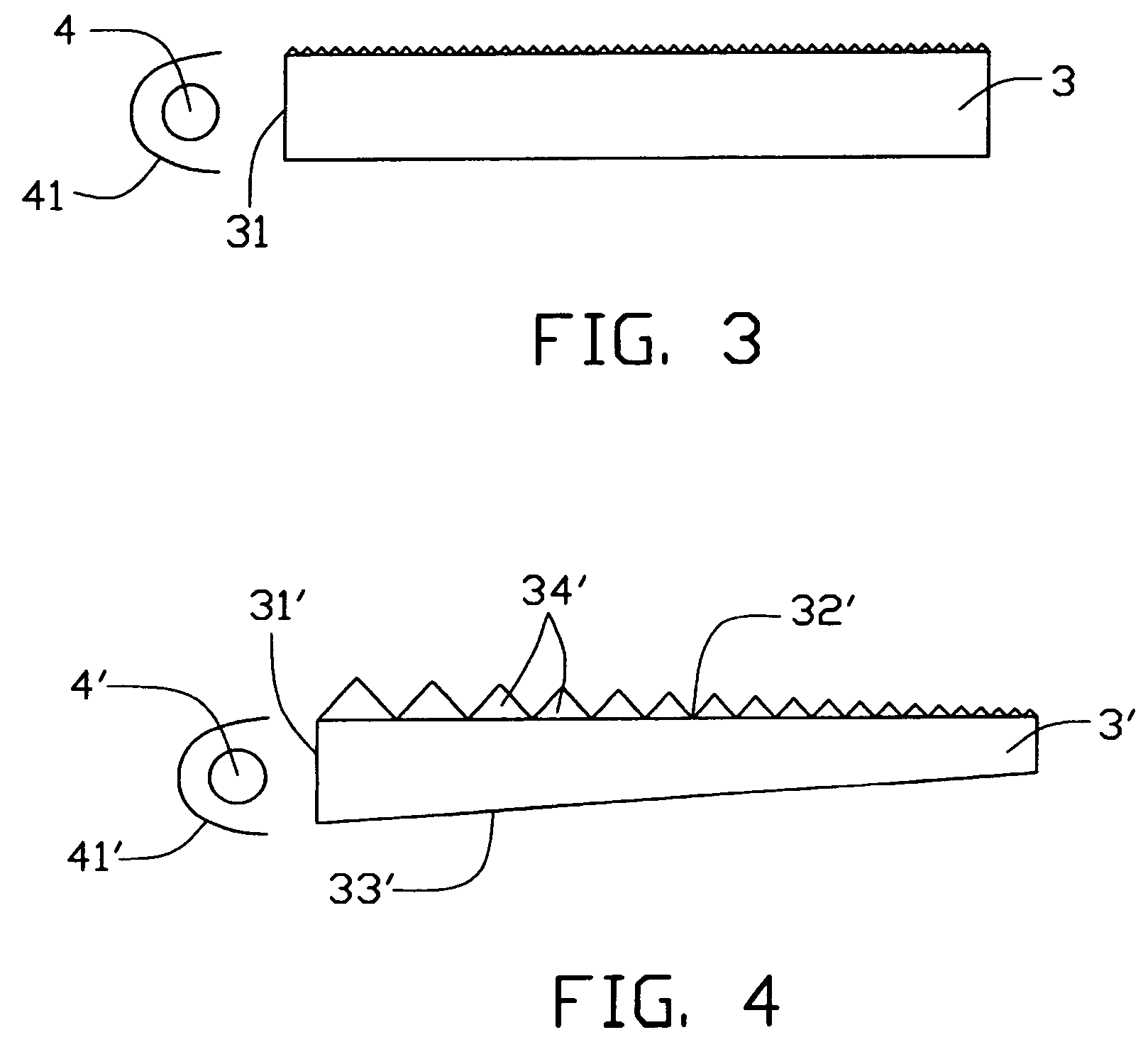
[0018]Referring to FIG. 1, a light guide plate 3 in accordance with a preferred embodiment of the present invention comprises a generally parallelepiped-shaped block having an input surface 31 for receiving light beams from a light source (not shown in FIG. 1), two side surfaces (not labeled) perpendicularly adjoining the incident surface 31, an output surface 32 perpendicularly adjoining the incident surface 31, and a bottom surface 33 opposite to the output surface 32. The block is generally made of a transparent material such as poly(acrylic acid), polycarbonate, polyethylene or glass.

[0019]Also referring to FIG. 2, a rectangular array of prisms 34 is integrally formed on the output surface 32 of the block. Each prism 34 is shaped as a square pyramid, in order to focus light beams emitting therefrom. All the prisms 34 have a same size and are arranged contiguously with each other in order...


PUM


Abstract

A light guide plate (3) includes a parallelepiped block. The block includes an input surface (31) for receiving light beams irradiated from a light source; two side surfaces perpendicularly adjoining the incident surface; an output surface (32) perpendicularly adjoining the incident surface and the side surfaces; and a bottom surface (33) opposing to the output surface. An array of prisms (34) is integrally formed on the output surface. Each prism is shaped as a square pyramid. All the prisms have a same size and are arranged contiguously with each other. Alternatively, the light guide plate may be a wedge-shaped block (3′). A rectangular array of prisms (34′) is integrally formed on an output surface (32′) thereof. Each prism is shaped as a square pyramid. The prisms are arranged contiguously with each other, and sizes of the prisms gradually decrease from a thick end to a thin end of the block.

Description

BACKGROUND OF THE INVENTION[0001]1. Field of the Invention[0002]The present invention relates to a light guide plate for use in a liquid crystal display; and more particularly to an improved light guide plate having enhanced light diffusion on a light output surface thereof, for use in a backlight system or a front light system of a liquid crystal display. This application relates to a contemporaneously filed application having the same title, the same applicants and the same assignee with the instant application.[0003]2. Description of Prior Art[0004]Liquid crystal materials cannot intrinsically emit light. Rather, a liquid crystal display must be equipped with an external light source. The so-called external light source is namely a backlight system or a front light system, which is used in conjunction with the liquid crystal display. A typical backlight or a front light system comprises a light guide plate for converting a point light source or a linear light source into a planar...

Claims


Application Information

Patent Timeline
Patent Type & Authority Patents(United States)
IPC IPC(8): F21V7/05F21V8/00
CPCG02B6/0036
Inventor YU, TAI-CHENGLEU, CHARLESCHEN, GA-LANE
Owner HON HAI PRECISION IND CO LTD
Why Eureka
Try Eureka