Sinewave dimmer control method

a sine wave dimmer and control method technology, applied in the direction of electric variable regulation, process and machine control, instruments, etc., can solve the problems of electrical noise and mechanical filament noise, requiring extensive filtering, and noise incident to phase angle dimming can be unacceptable, so as to minimize undesirable voltage transients, maximize efficient power transfer, and maximize power coupling

Inactive Publication Date: 2006-03-28
ELECTRONIC THEATRE CONTROLS
View PDF8 Cites 33 Cited by
  • Summary
  • Abstract
  • Description
  • Claims
  • Application Information

AI Technical Summary

Benefits of technology

[0012]A primary object of the present invention is to provide an improved method for controlling a synchronous sinewave dimmer. Other objects are to provide an improved sinewave dimmer control method that provides efficient power coupling through an output filter and load for both resistive and reactive loads; to provide an improved sinewave dimmer control method for precisely controlling the alternate switching sequence of the series and clamp switching devices; to provide an improved sinewave dimmer control method that maximizes efficient power transfer to a load and that minimizes undesirable voltage transients; to provide an improved sinewave dimmer control method that avoids overlapping conduction of the series and clamp switching devices; to provide an improved sinewave dimmer control method that avoids simultaneous nonconduction of the series and clamp switching devices; and to provide a sinewave dimmer control method that overcomes difficulties experienced with prior art methods.

Problems solved by technology

With a phase angle dimmer, the abrupt low frequency switching during the half cycles of the power supply and resultant abrupt amplitude changes in the current supplied to a luminaire can cause problems of electrical noise and mechanical filament noise, requiring extensive filtering.
In some dimmer applications, even with filtering, the noise incident to phase angle dimming can be unacceptable.
In addition, phase angle dimmers have the disadvantage that they can reflect harmonic distortion into the mains power supply.
One problem is maintaining precise control of the clamp switching section close to the power supply zero crossing points.
Another difficulty arises when the load is reactive, or when the load is small in relation to the output filter inductance, and the power supply voltage and current are not in phase.
A potential problem with synchronous dimmers results from the alternate series and clamp switching sequence.
This could result in excessive current flow and heat and damage to circuit components including the switches.
However, this can introduce a time period during which neither the series switch nor the clamp switch is conducting.
During this time period the lack of a flow path for current through the output filter could result in voltage spikes and an adverse effect on circuit component life and on the output power waveform.

Method used


Image

  • Sinewave dimmer control method
  • Sinewave dimmer control method
  • Sinewave dimmer control method

Examples


Embodiment Construction

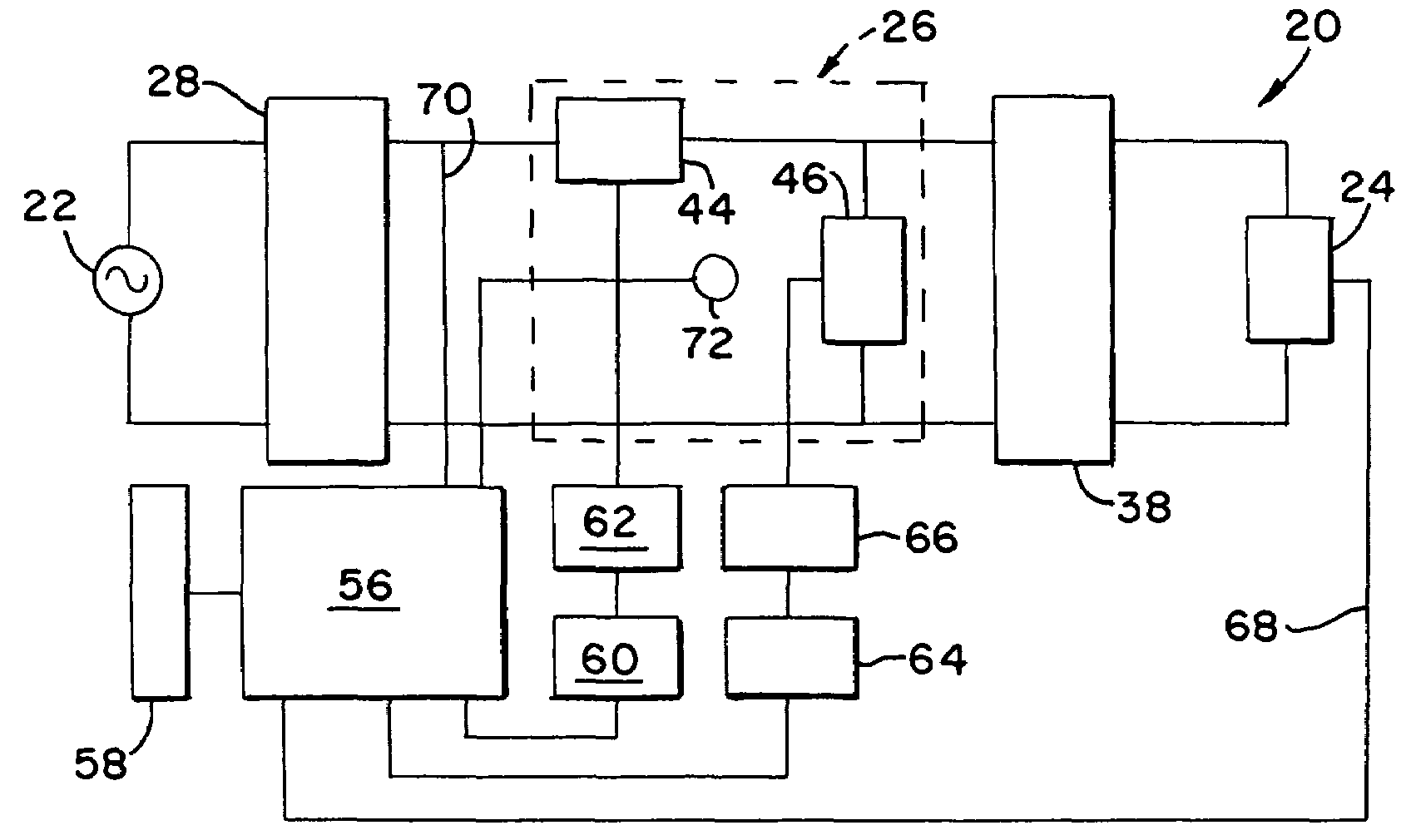
[0024]Having reference now to the drawing, FIG. 1 is a simplified block diagram of a synchronous sinewave dimmer designated as a whole by the reference character 20. The dimmer 20 is connected to a conventional mains power supply 22 providing a sinusoidal alternating current power supply waveform of, for example, nominal 120 volts ac. The dimmer 20 provides output power to a load 24. In a typical application, the load 24 may be a resistive load such as an incandescent lamp, or a reactive load such as a power supply for a gas discharge lamp or fluorescent lamp. A power switching stage 26 uses pulse width modulation (PWM) to attenuate input power and supply reduced output power to the load.

[0025]An input line filter 28 filters out noise that may be present on the power supply signal and assures the supply of clean ac power to the power switching stage 26. In addition the input line filter 28 filters out switching noise from the power switching stage 26 and prevents the conduction of n...


PUM


Abstract

An input line filter separates an ac sinusoidal power source from a power switching stage having a series switching section and a clamp switching section. Both the series switching section and a clamp switching section include complementary pairs of high power and high speed MOSFETs. The series switching section is connected in series between the input line filter and the inductor of an output load filter between the power switching stage and a load. The clamp switching section is connected to shunt the inductor and load. Synchronous operation is achieved by alternately operating the series and clamp switching sections to conductive conditions at a high pulse width modulation frequency. The duty cycle is selected to provide a sinusoidal output waveform with a desired amplitude. A microprocessor based programmable controller provides control signals for alternate conduction of the series and clamp switching sections. A dead time interval stored in memory in the controller separates the control signals for reliable and efficient operation. The dead time interval may be constant, or may be varied in accordance with load power variations.

Description

FIELD OF THE INVENTION[0001]The present invention relates to a method for controlling a sinewave dimmer in order to achieve reliable operation and efficient power transfer through an inductive dimmer output filter.DESCRIPTION OF THE PRIOR ART[0002]A lamp may be provided with power by a dimmer so that the lamp can be operated at variable, selected light intensity levels. For example, luminaires for theatrical, architectural and other applications are often provided with operating power by dimmers. Phase angle dimmers for this purpose are well known, and typically include solid state switches such as SCRs for interconnecting an AC power source to a lamp load. AC voltage from the source is sinusoidal. A phase control circuit renders a solid state switch conductive at a point during a half cycle of the sinusoid, the point being selected to supply to the lamp a lamp operating pulse having a desired quantity of power in order to produce a desired level of light intensity. Switching operat...

Claims


Application Information

Patent Timeline
Patent Type & Authority Patents(United States)
IPC IPC(8): H05B37/00
CPCH02M1/38H02M5/293H05B41/3924H05B39/048Y10S315/04
Inventor THURK, JOHN P.SUOMI, ERIC W.RASMUSSEN, ERIC G.
Owner ELECTRONIC THEATRE CONTROLS
Why Eureka
Try Eureka