Optical deflector and optical scanner having the optical deflector

Inactive Publication Date: 2006-03-28
FUJIFILM BUSINESS INNOVATION CORP
View PDF4 Cites 8 Cited by
  • Summary
  • Abstract
  • Description
  • Claims
  • Application Information

AI Technical Summary

Benefits of technology

[0021]The present invention has been made in view of the above facts and provides an optical deflector capable of reducing a rise in the heat of integrated circuits and a housing without increasing noises caused by the wind sound of a rotative polygon mirror, and an optical scanner having the optical deflector.
[0025]Furthermore, since the radiating member is brought into contact with the electronic part through the first through hole formed on the lower face of the integrated circuit, the radiating member is not exposed to an upper portion of the drive circuit board, that is, a side in which a rotative polygon mirror is disposed. Therefore, bringing the radiating member into contact with the electronic part does not result in increased wind sound generated during the rotation of the rotative polygon mirror.
[0034]According to the above aspect, by bringing the radiating member into contact with the electronic part through the first through hole, beat of the electronic part can be conducted to the radiating member through which the heat of the electronic part can be radiated. By forming the first through hole on the lower face of the integrated circuit as the electronic part and bringing the radiating member into contact with the integrated circuit through the first through hole, a rise in the temperature of the housing can be reduced. As a result, the life of a bearing constituting the motor can be prolonged and the reliability of the integrated circuit can be increased.
[0035]Since the radiating member is brought into direct contact with the integrated circuit, the radiation efficiency of the integrated circuit is excellent. Furthermore, by bringing the radiating member into contact with the drive circuit board, the first through hole is blocked by the radiating member and the optical scanner is kept sealed.

Problems solved by technology

However, it is often made of a material having a low thermal conductivity such as resin because of its low cost and constructionally has difficulty in expelling heat within the housing 228 to the outside.
However, since laser printers are becoming higher in image quality and printing speeds are becoming faster, when a rotative polygon mirror is fast rotated to scan a laser beam on a photoconductive material, currents consumed by a rotating body and integrated circuits become larger in proportion to the speed of the rotating body as shown in FIG. 22, heat generated from an optical deflector increases, and the temperature of the housing of an optical scanner also rises.
Furthermore, in recent years, small and flat integrated circuits are mounted on the surface of a printed board and are not structured to have a radiating member mounted therein.
Therefore, in cases where a radiating member is secured by an adhesive having an excellent thermal conductivity, the thermal resistance of the adhesive and the time required until the radiating member has been secured become a problem.
On the other hand, although there is a method of using tightening members such as screws to mechanically tighten and secure a radiating member to an integrated circuit, holes for the tightening members must be provided on a printed board, so that a securing method becomes complicated and the printed board becomes large in size.
As a result, the radiating member 248 has a complicated positioning structure, which causes a rise in costs.

Method used


Image

  • Optical deflector and optical scanner having the optical deflector
  • Optical deflector and optical scanner having the optical deflector
  • Optical deflector and optical scanner having the optical deflector

Examples


first embodiment

[0059]Hereinafter, an optical scanner of the present invention is described.

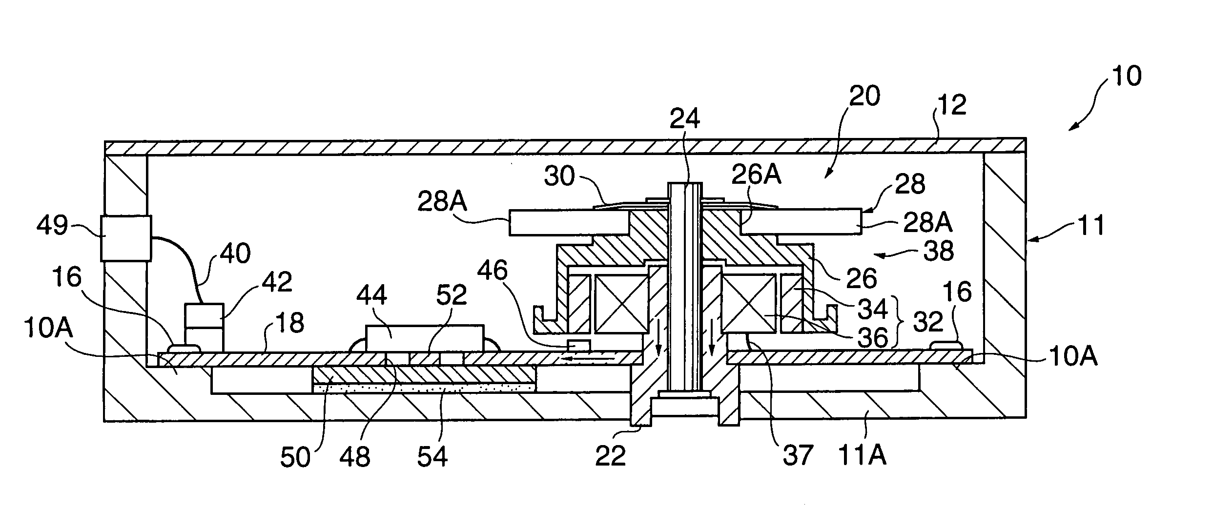
[0060]FIG. 1 is a sectional view of an optical scanner 10, which is formed in box shape and substantially sealed with its opening covered with a cover 12. Seats 10A are projectingly mounted in the corners of a bottom wall 11a of a housing 11 of the optical scanner 10, and a metallic printed board 18 is secured by mounting screws 16.

[0061]A substantially cylindrical bearing 22 with a bottom constituting an optical deflector 20 penetrates through the printed board 18, and a rotation shaft 24 is fitted in the bearing 22 and rotatably supported.

[0062]A substantially tube-like rotation sleeve 26 is secured in an upper portion of the rotation shaft 24 and is rotatable integrally with the rotation shaft 24. In an upper portion of the rotation sleeve 26 is provided a small-diameter portion 26A, around which a polygon mirror 28 configured with plural mirrors 28A is fitted and secured to the rotation sleeve 26 by a ri...

second embodiment

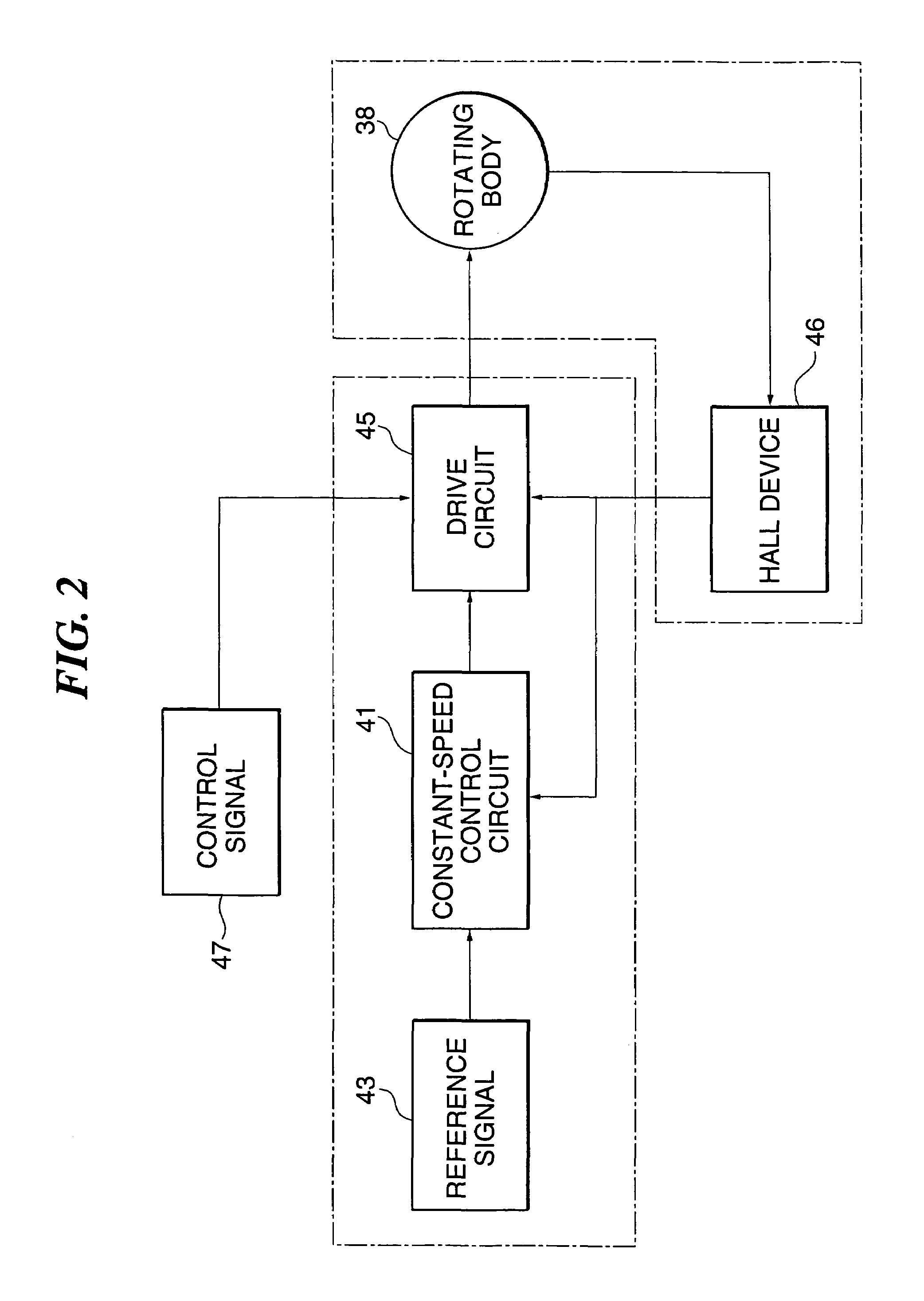
[0091]The following describes the operation of the optical scanner of the present invention.

[0092]As shown in FIG. 5, by making the housing 62 itself of the optical scanner 60 a radiating member, heat generated by the integrated circuit 44 is radiated to the outside through the silicon rubber 66 and the seat 64.

[0093]Heat within the housing 62 generated by the motor 32 can be radiated through the printed board 18, the silicon rubber 66, and the seat 64. Therefore, without using a special radiating member, a rise in the temperature in the integrated circuit 44 and the housing 62 can be reduced.

[0094]Furthermore, by providing the clearance 69 between the mount 68 provided in the laser printer and the back of the optical scanner 60, and providing the mount 68 with a cooling unit such as the fan 70, air outside the housing 69 is allowed to flow to the clearance 69 and the bottom wall 62A of the housing 62 is cooled, and heat radiated by the housing 62 is allowed to flow in a direction t...

third embodiment

[0104]The following describes the operation of the optical scanner of the present invention.

[0105]As shown in FIG. 6, the mounting part 76 is projectingly mounted in the bottom wall 74A of the housing 74 and provided with the through hole 78 corresponding to the through hole 48. By inserting the ribs 80B of the radiating member 80 in the through hole 78, the ribs 80B are exposed to outside the housing 74.

[0106]With this construction, heat generated from the integrated circuit 44 and the motor 32 can be radiated to outside the housing 74 through the radiating member 80. Therefore, a rise in the temperature in the integrated circuit 44 and the housing 74 can be reduced.

[0107]With the printed board 18 secured to the seats 72A, the height of the radiating member 80 disposed on the elastic member 82 is higher than a clearance between the printed board 18 and the upper face of the mounting part 76, and the elastic member 84 is formed so as to be thicker than the printed board 18.

[0108]Wit...


PUM


Abstract

The present invention provides an optical deflector capable of reducing a rise in heat of integrated circuits and a housing without increasing noises caused by a wind sound of a rotative polygon mirror, and an optical scanner having the optical deflector. Heat in a lower face of an integrated circuit of a printed board can be allowed to escape by providing a through hole in a lower position of the integrated circuit. By bringing a radiating member into direct contact with the integrated circuit through the through hole, heat of the integrated circuit can be conducted to the radiating member and radiated. Therefore, a rise in a temperature of the housing can be reduced. As a result, life of a bearing can be prolonged and reliability of the integrated circuit can be increased.

Description

BACKGROUND OF THE INVENTION[0001]1. Field of the Invention[0002]The present invention relates to an optical deflector used in a laser printer and the like, and an optical scanner having the optical deflector.[0003]2. Description of Related Art[0004]FIG. 17 shows a general laser printer 200. As shown in FIGS. 17 and 18, an optical scanner 202 of box shape is disposed within the laser printer 200, and a light beam is emitted from a light source 204 disposed in a side wall of the optical scanner 202.[0005]The light beam passes through a collimator lens 206, is reflected by one reflection face of a polygon mirror 214 constituting an optical deflector 212, and inputted to a surface of a photoconductive material 220 used as a drum-like recording medium via fθ lens 216 and cylindrical mirror 218, so that a latent image is formed on the photoconductive material 220.[0006]As shown in FIG. 19, the optical deflector 212 is secured to the optical scanner 202 and a rotating body 222 including th...

Claims


Application Information

Patent Timeline
IPC IPC(8): G02B26/08G02B26/10G02B26/12H04N1/113H05K1/02
CPCG02B26/121H04N1/113H05K1/0206
Inventor MIKAMI, KEIICHI
Owner FUJIFILM BUSINESS INNOVATION CORP
Why Eureka
Try Eureka