Outdoor lighting system

a technology for outdoor lighting and outdoor lighting, which is applied in the field of outdoor landscape lighting, can solve the problems of low-voltage lighting systems, inability to utilize remote locations away from an ac outlet, and extremely limited size and number of rechargeable batteries, and achieves low power consumption, not generating much heat, and high light intensity output.

Inactive Publication Date: 2006-04-04
LAKESOUTH HLDG LLC
View PDF8 Cites 99 Cited by
  • Summary
  • Abstract
  • Description
  • Claims
  • Application Information

AI Technical Summary

Benefits of technology

[0011]It is one objective of the present invention to provide a lawn or patio umbrella with an integral lighting system that utilizes a cold cathode ray tube to provide relatively bright outdoor light for reading and other relatively high light intensity activities.
[0013]It is yet another objective of the present invention to provide a lawn or patio umbrella that includes a cold cathode ray tube lighting system and an electrically-actuated motorized retraction subassembly that allows the umbrella to be opened and closed more easily.Lawn Lighting Systems
[0016]It is another objective of the present invention to provide a photovoltaic solar cell that is utilized to convert sunlight into electrical energy to recharge the rechargeable battery or battery pack carried by the cold cathode ray tube lighting fixture. In one particular embodiment of the present invention, each lighting fixture carries its own solar cell. In another particular embodiment of the present invention, a remotely located solar cell panel is utilized to recharge a plurality of batteries or battery packs contained in a number of light fixtures that are all connected together by electrical conductors. This remotely located photovoltaic solar cell panel may provide the sole means for recharging the battery packs, or it may supplement charging performed by photovoltaic solar cells carried on each individual lighting fixture.Cold Cathode Ray Tubes for Outdoor Lighting
[0017]It is another objective of the present invention to utilize a cold cathode ray tube as the primary bulb for an outdoor lighting fixture that is independent of any household electrical systems. The cold cathode ray tube is a relatively low power consuming device, does not generate much heat, provides a high amount of light intensity output from the bulb, reduces the overall energy consumption of the outdoor lighting fixture, allows for fewer batteries to be utilized in each lighting fixture, allows for easier recharging of the batteries due to the lower power requirements, and allows the utilization of smaller photovoltaic solar cells. One additional advantage of utilizing a cold cathode ray tube is that it may be operated at multiple voltage levels to provide differing amounts of light output. In one particular embodiment, a wireless receiver and transmitter pair may be utilized to allow an operator to use a wireless command signal to change the operating state of a lawn lighting system, and in particular may be utilized to switch the system between on and off conditions, and to switch the system between varying levels of light output. Accordingly, an operator may intensify the light output from a lawn lighting system through use of a wireless handheld transmitter if he needs additional light at a particular location, such as a particular pathway, patio, lawn, or other outdoor structure or feature.

Problems solved by technology

There are several problems associated with such low-voltage lighting systems.
For example, they must be plugged into a conventional AC power outlet to receive power, the incandescent bulbs do not provide high intensity light, and the they cannot be utilized in remote locations away from an AC outlet.
The are also problems associated with these types of lighting systems.
For example, the size and number of the rechargeable batteries is extremely limited, resulting in short periods of illumination, the incandescent bulbs do not provide high intensity light, and the lighting fixtures must operate independently of each other.

Method used


Image

  • Outdoor lighting system
  • Outdoor lighting system
  • Outdoor lighting system

Examples


first embodiment

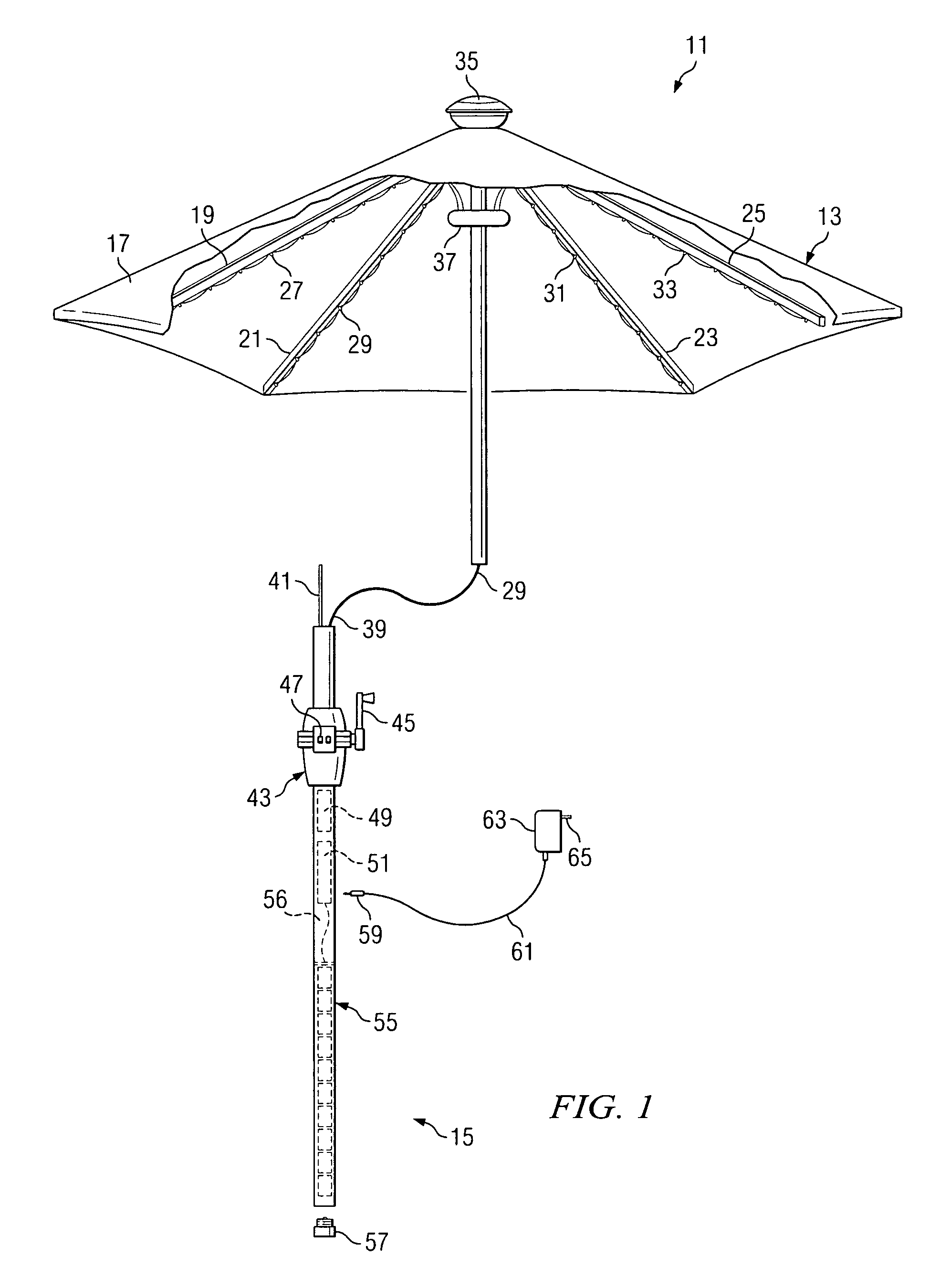
[0036]FIG. 1 is a view of the present invention. It is directed to an improved umbrella 11 which includes an integral lighted system and a motorized retraction system which allows one to open and close the umbrella canopy through the push of a button. Preferably, the lighting system utilizes a cold cathode ray tube which will be described in greater detail below. As is shown in FIG. 1, improved umbrella 11 includes an umbrella portion 13 and a pole portion 15. The view of FIG. 1 does not include the view of a base member which is typical or conventional for use with umbrellas. The other embodiments show a variety of conventional and novel base members, any of which can be utilized with the embodiment of FIG. 1. Alternatively, the embodiment of FIG. 1 (as well as the other embodiments) can be utilized with little or no base member whatsoever provided that there is a table with a center aperture adapted in size and shape to receive the pole portion 15 of the improved umbrella 11. In o...

third embodiment

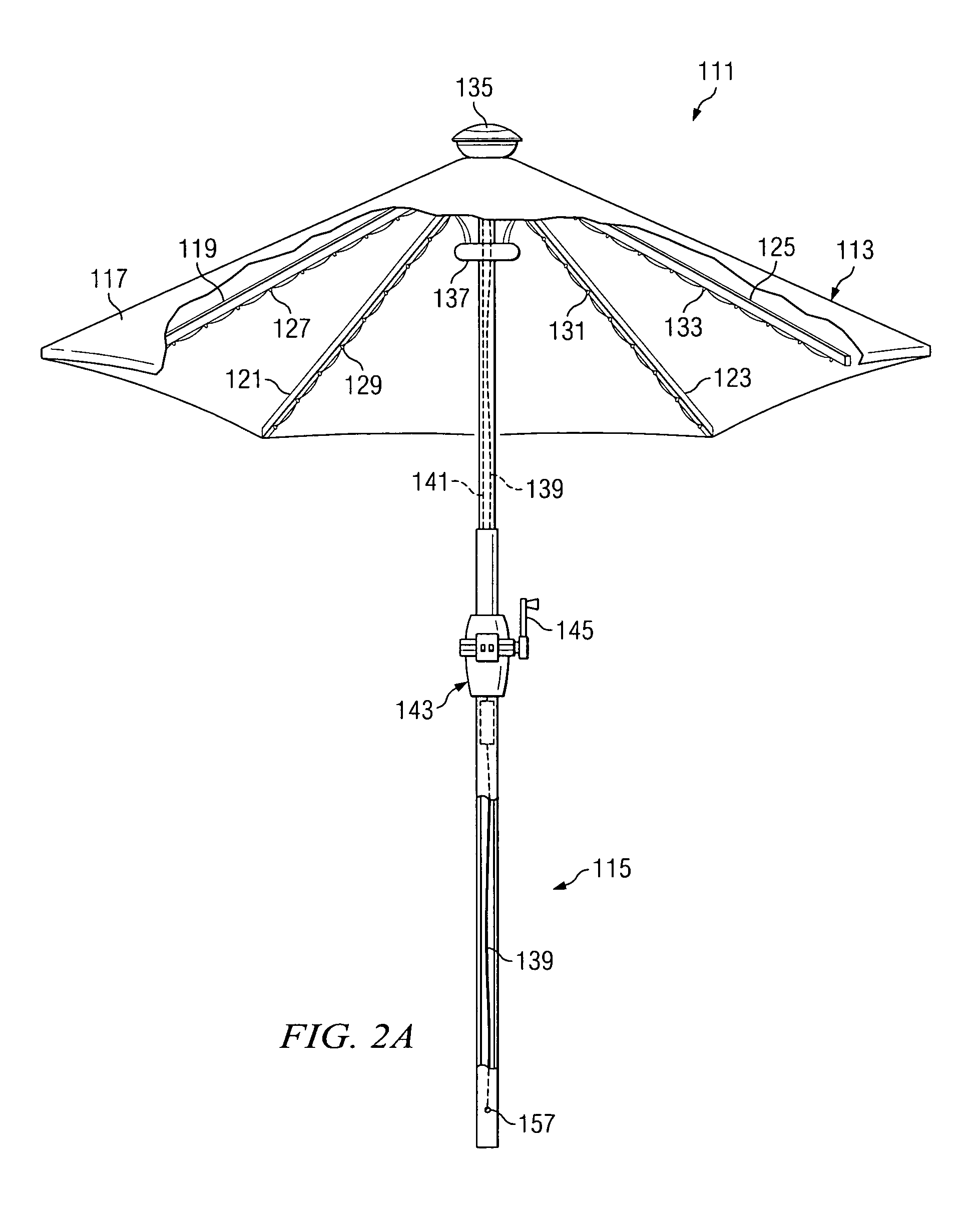
[0047]As is shown in FIG. 3A, an improved umbrella 211 includes an umbrella portion 213 and a pole portion 215. Umbrella 211 includes a canopy 217 that can be opened and closed. Umbrella 211 further includes a plurality of ribs 219, 221, 223, and 225 that carry a number of light strands 227, 229, 231, and 233. Light strands 227, 229, 231, and 233 each contain a number of small cold cathode ray tube bulbs and associated wiring. A solar cell 235 is carried at upper cap portion of the improved umbrella 211. Solar cell 235 is provided to provide a trickle charge to rechargeable batteries 277 associated with the lighted umbrella. As is shown, a wiring ring 237 is provided to route wiring 239 into the hollow central portion of the stand portion 215. As in the previous embodiments, a cable system 241 is also routed through the hollow central portion of stand portion 215 and is utilized to open and close the umbrella canopy 217. A pulley system 243 and a crank 245 are provided to allow the ...

fourth embodiment

[0050]FIG. 4A depicts a fourth embodiment in which the lighting elements are recessed into a rib member, such as rib member 301. FIG. 4A is a fragmentary and sectional view of a rib 301. As is shown, a cavity 303 is formed within rib 301 and adapted to receive and hold light bulb 307. A translucent material 305 is provided to cover the cavity 303 and an array of bulbs 307 is maintained within the cavity 303 along the length of rib 301. According to the preferred embodiment, bulb 307 is a cold cathode ray tube bulb. In practice, there may be many bulbs 307 extending along the length of rib 301 to illuminate the area under the umbrella. As is shown, a wiring cavity 309 is provided which joins the cavity 303. Wiring 311 is passed through this wiring cavity 309 and provides a circuit for the plurality of bulbs 307 carried by rib 301. The translucent material extends along the entire length of the cavity 303 of rib 301. The result is a recessed lighting that is carried entirely within th...


PUM


Abstract

An outdoor lighting system is disclosed. The individual lights are self-powered by one or more batteries carried in the lighting structure itself. In one embodiment, one or more rechargeable batteries are located within a relatively elongated base structure of the lighting component. In one particular embodiment, this elongated base structure also serves as a stake that is utilized to fix the lighting fixture in a particular outdoor location, such as a lawn, pathway, driveway, or patio.

Description

[0001]This application claims the benefit of U.S. Provisional Application No. 60 / 335,933, filed 2 Nov. 2001, titled “Outdoor Lighting System with Cold cathode ray tubes.”BACKGROUND[0002]1. Field of the Invention[0003]The present invention relates to outdoor lighting. In particular, the present invention relates to outdoor landscape lighting.[0004]2. Description of Related Art[0005]Outdoor lighting systems have been around for many years. However, low-cost, automated low-voltage lighting systems are a relatively recent introduction into the outdoor lighting market. These low-voltage systems typically include a plurality of lighting fixtures wired together and to a control box. The lighting elements in the lighting fixtures are typically 4-Volt or 11-Volt incandescent bulbs. The control box typically plugs into a conventional AC power outlet and includes the necessary voltage regulators, AC to DC converters, on-off switches, and optional timers.[0006]There are several problems associa...

Claims


Application Information

Patent Timeline
Patent Type & Authority Patents(United States)
IPC IPC(8): A45B3/04F21V33/00
CPCA45B3/04F21S9/032F21V21/0824A45B2200/1027A45B2200/1045F21S2/00F21W2131/10F21W2131/109Y02B20/72
Inventor KUELBS, GREGORY G.
Owner LAKESOUTH HLDG LLC
Why Eureka
Try Eureka