Apparatus for shaping and perforating a plastic film

a technology of plastic film and perforation, which is applied in the field of plastic article shaping apparatus, can solve the problems of little force applied to the mold, mold disposed to erode much, and little flexibility in the geometry of the pattern to be formed, and achieve the effect of increasing mechanical strength

Inactive Publication Date: 2006-04-04
REUM SR DONALD J
View PDF18 Cites 7 Cited by
  • Summary
  • Abstract
  • Description
  • Claims
  • Application Information

AI Technical Summary

Benefits of technology

[0015]Exemplary embodiments of the present invention solve inadequacies of the prior art by providing a vacuum forming roll which is assembled from a large plurality of radially extensive interlocking segments. Each segment forms a small angular part of a circumference about the roll, and has a relatively small thickness parallel to the longitudinal axis of the roll. The segments are preferably stacked together in an interlocking fashion to form a continuous roll consisting of a plurality of angularly offset circumferential rings. In the preferred embodiment, the segments are formed by manufacturing a small mold designed to form a single segment. This mold may, for exemplary purposes, be an injection mold. The roll mold segments may then be produced quickly and easily using an injection molding process, which, as aforementioned, is efficient for the production of a large number of identical components. The roll mold segments are then assembled to form the roll mold, which is in turn used to fabricate improved landscape fabric economically.
[0017]In a second manifestation, the invention is a method of manufacturing and using a vacuum thermoforming mold. According to the method, a mold is fabricated to have a shape defining surface. A plurality of segments are formed through contact with the shape defining surface. Ones of the plurality of segments are arranged in contact with and offset with respect to adjacent ones of the plurality of segments to thereby assemble a vacuum form. Differential pressure is selectively applied through the vacuum form while passing a plasticized film adjacent thereto, to thereby reshape and perforate the plastic film.
[0019]A first object of the invention is to form a large mold from smaller mold segments. A second object of the invention is to configure the mold segments to be manufactured by molding. Another object of the present invention is to enable the production of precise and detailed three-dimensional geometries from ordinary plastic sheet. A further object of the invention is to provide a plurality of ports for pressure control, which may in turn be used for the ejection of residue when required. Yet another object of the present invention is to control the temperature of the mold segments as needed for the fabrication of a particular thickness and composition of plastic sheet. A further object of the invention is to overlap and stagger all end-to-end joints between mold segments, to thereby form an interlocking between components which substantially increases mechanical strength within a cumulative collection of segments such as a roll or full mold.

Problems solved by technology

However, when vacuum thermoforming relatively softer and more readily formed materials, such as thin or soft thermoplastic sheets, very little force will ever be applied to the mold, nor will the mold be disposed to erode much.
Unfortunately, there is very little flexibility in the geometry of the pattern to be formed, nor, where apertures are desired, in the geometry of and adjacent to the aperture.
Such production techniques are quite hazardous, expensive, and still only effect microscopic features in the generally two-dimensional sheet.
Consequently, this technology has been limited to the forming of primarily flat sheet products, or those products that are dimpled or perforated in repeating pattern corresponding to the holes.
These sheets are commonly imperforate, and consequently block sunlight or plants from passing through.
Unfortunately, these imperforate materials prevent moisture and air from passing through also, and so are typically cut in a large perimeter adjacent the plants to permit adequate water and air to reach the plants and soil.
Unfortunately, this also permits weeds to grow adjacent the plant.
Unfortunately, plant roots are sometimes extremely fine and also pass through the non-woven fabrics, enabling a plant to undesirably grow on top of the fabric while degrading the effectiveness of the fabric.
These non-woven fabrics are additionally somewhat more expensive and less durable than the imperforate sheets or films of plastic.
Drainage channels conveniently direct moisture through the perforations, while sunlight is generally blocked, owing to the generally vertical nature of the perforate walls.
However, and as is apparent in the illustrations, the fabric must be formed with relatively complex three-dimensional patterns into an indeterminate length film.
Unfortunately, the fabrication of a vacuum roll form using prior art techniques such as described by the prior art referenced herein above and incorporated herein by reference requires substantial, almost astronomical expense.
The prior art technique to achieve this removal is substantial, very repetitive machining.
Consequently, the cost of the tooling required for the production of large volumes of the improved fabric has prevented substantial adoption of the fabric within the landscaping industry to date.

Method used


Image

  • Apparatus for shaping and perforating a plastic film
  • Apparatus for shaping and perforating a plastic film
  • Apparatus for shaping and perforating a plastic film

Examples


Embodiment Construction

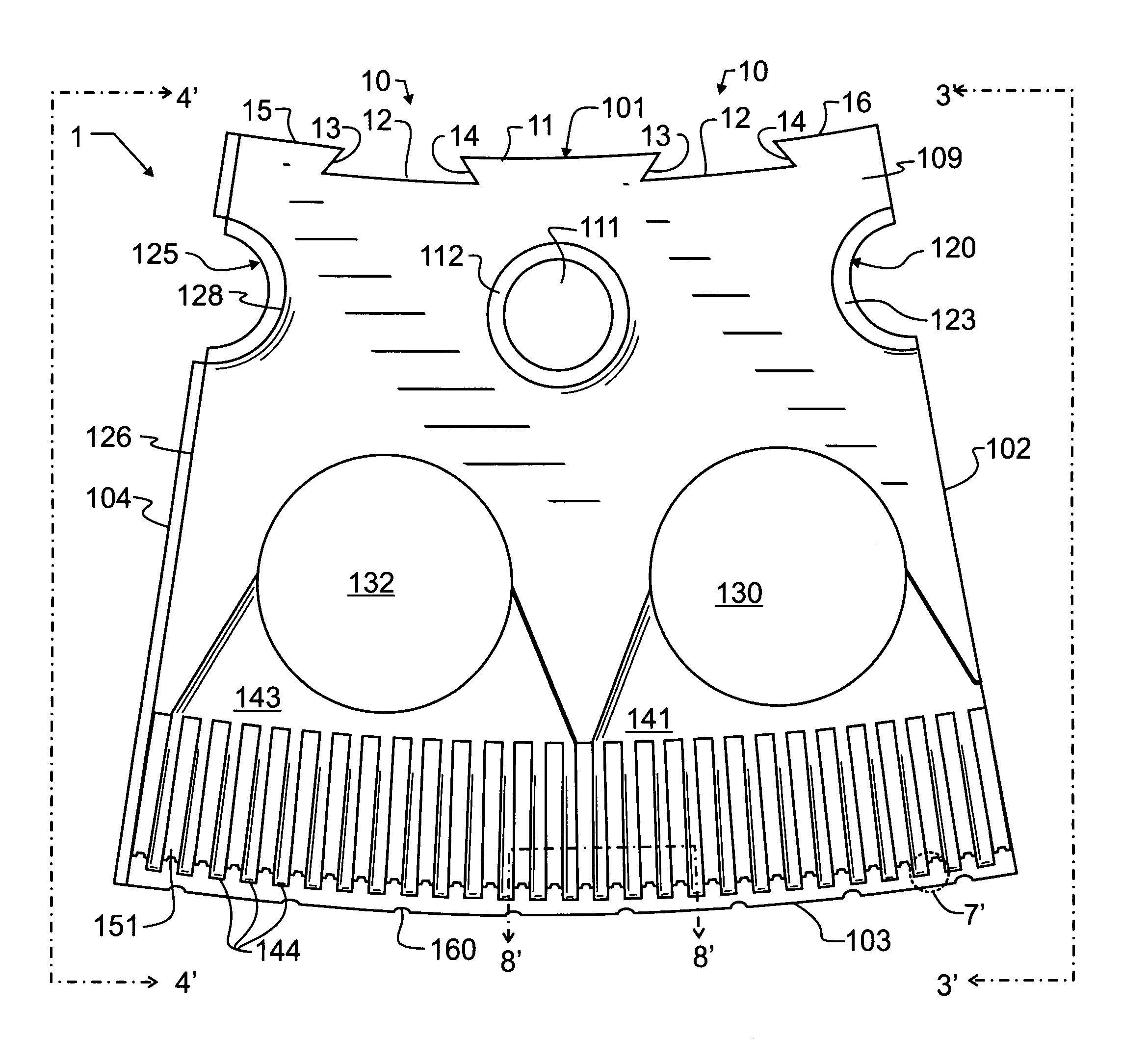
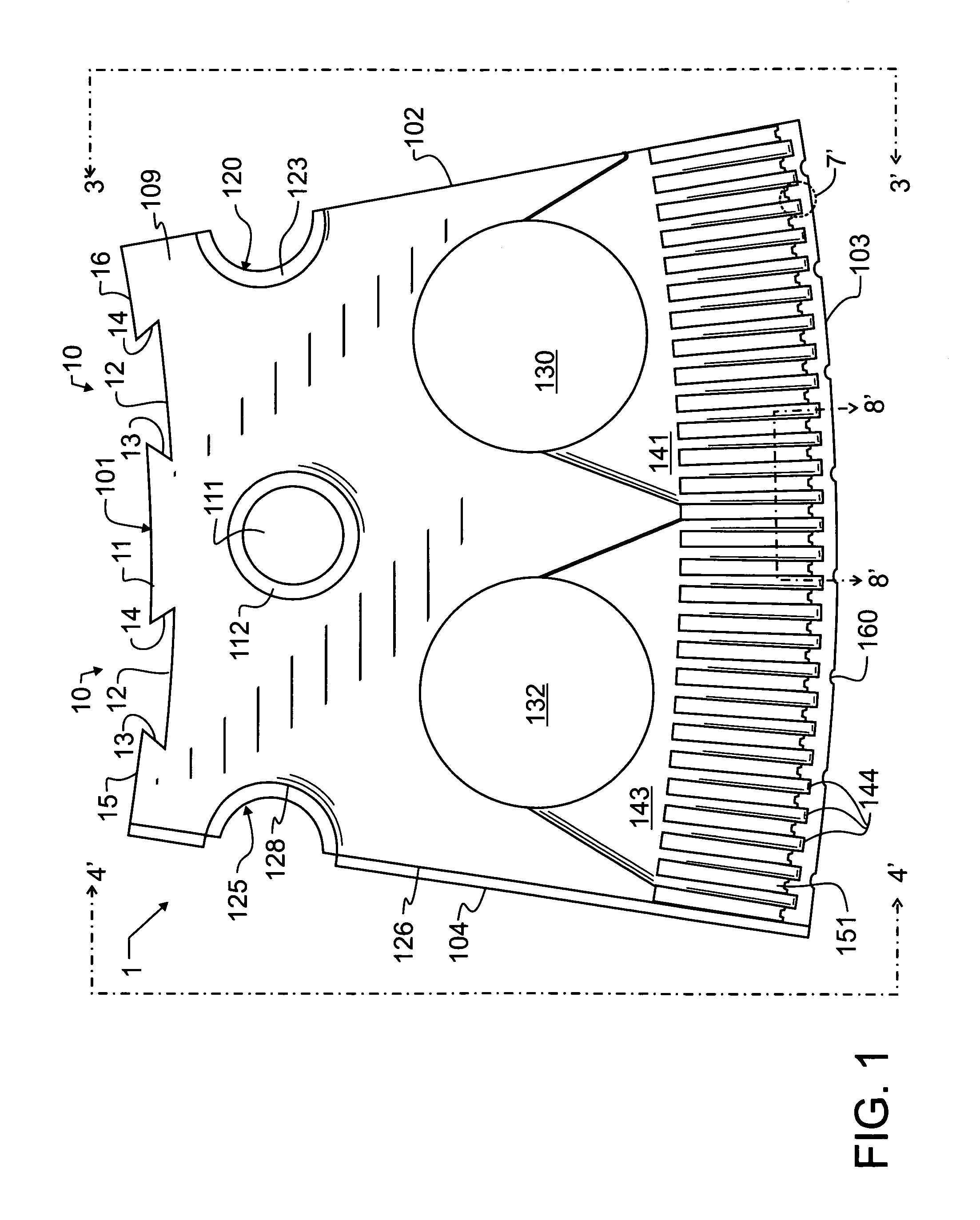
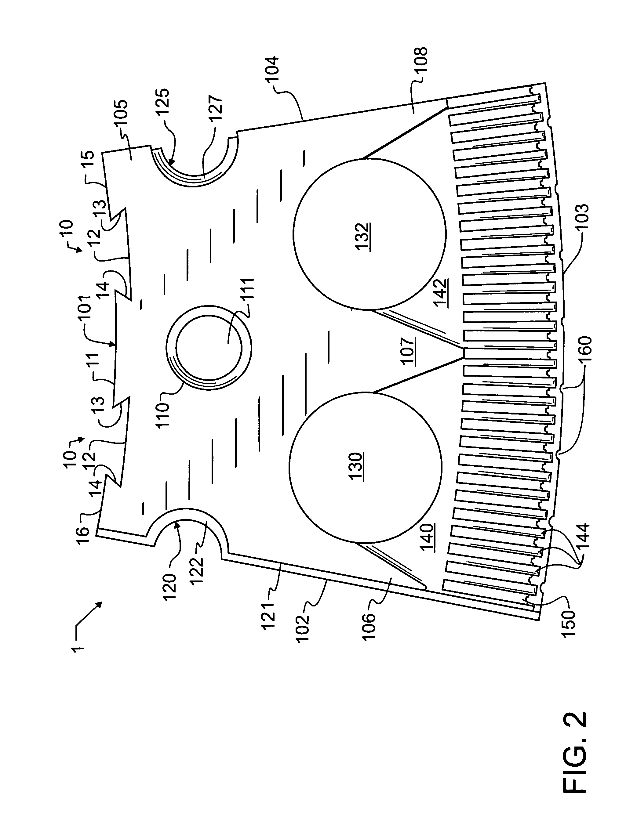
[0029]In accord with the teachings of the present invention, and to illustrate the concepts encompassed therein, preferred embodiment single mold segment 1 is illustrated in FIGS. 1–4 and 7. A preferred embodiment roll 200 which combines a plurality of adjacent and angularly offset circumferential rings 201, each circumferential ring 201 made up of a plurality of like single mold segments 1, is illustrated in FIGS. 5, 6 and 8.

[0030]Segment 1 has a first major planar surface 109 forming a first face and a second parallel major planar surface 105 forming a second opposed face. Central edge 101 forms a first minor surface bounding mold segment 1, and includes several trapezoidal notches 10 therein, described in greater detail herein below. Exterior edge 103 forms a second minor surface, and composite edges 102, 121 and 104, 126 form the third and fourth minor surfaces, respectively. These four minor surfaces together with the two major surfaces 105, 109 generally define the exterior sp...


PUM

PropertyMeasurementUnit
pressureaaaaaaaaaa
circumferenceaaaaaaaaaa
thicknessaaaaaaaaaa

Abstract

A vacuum forming roll is assembled from a large plurality of radially extensive interlocking segments. Each segment forms a small angular part of a circumference about the roll, and has a relatively small thickness parallel to the longitudinal axis of the roll. The segments are preferably stacked together in an interlocking fashion to form a continuous roll consisting of a plurality of angularly offset circumferential rings. In a preferred embodiment, the segments are formed by manufacturing a small mold designed to form a single segment. This mold may, for exemplary purposes, be an injection mold. The roll mold segments may then be produced quickly and easily using an injection molding process, which, as aforementioned, is efficient for the production of a large number of identical components. The roll mold segments are then assembled to form the roll mold, which is in turn used to shape and perforate a plastic film and thereby manufacture an improved landscape fabric economically. A variety of shapes, geometries and operations for the segments and molds are described.

Description

BACKGROUND OF THE INVENTION[0001]1. Field of the Invention[0002]This invention pertains generally to plastic article shaping apparatus, and more specifically to preform reshaping using vacuum or suction. The preferred reshaping is accomplished at least in part by creating a reduced pressure on at least one surface of a plastic sheet to provide a differential pressure which is utilized as a shaping force. In one preferred manifestation of the invention, the apparatus is used to form landscape fabric from an indeterminate length web, roll, or spool of plastic film.[0003]2. Description of the Related Art[0004]Modern plastic materials have many desirable features and characteristics that make them advantageously suited for many diverse applications. Among the characteristics is the ability to be formed into diverse shapes. One such shape of interest in the present invention is that of a large sheet of very consistent thickness and nearly indefinite length, referred to herein more simply...

Claims


Application Information

Patent Timeline
Patent Type & Authority Patents(United States)
IPC IPC(8): B29C59/04
CPCB29C59/06B26F1/26
Inventor REUM, SR., DONALD J.
Owner REUM SR DONALD J
Why Eureka
Try Eureka