Fluidic device for medical diagnostics

a technology of medical diagnostics and fluid flow, which is applied in the field of fluid flow diagnostic devices, can solve the problems of limited control of fluid flow into the indicator,

Inactive Publication Date: 2006-04-04
LIFESCAN IP HLDG LLC
View PDF64 Cites 129 Cited by
  • Summary
  • Abstract
  • Description
  • Claims
  • Application Information

AI Technical Summary

Problems solved by technology

As with the Davis device, discussed above, control of fluid flow into the indicator is very limited.

Method used


Image

  • Fluidic device for medical diagnostics
  • Fluidic device for medical diagnostics
  • Fluidic device for medical diagnostics

Examples


example 1

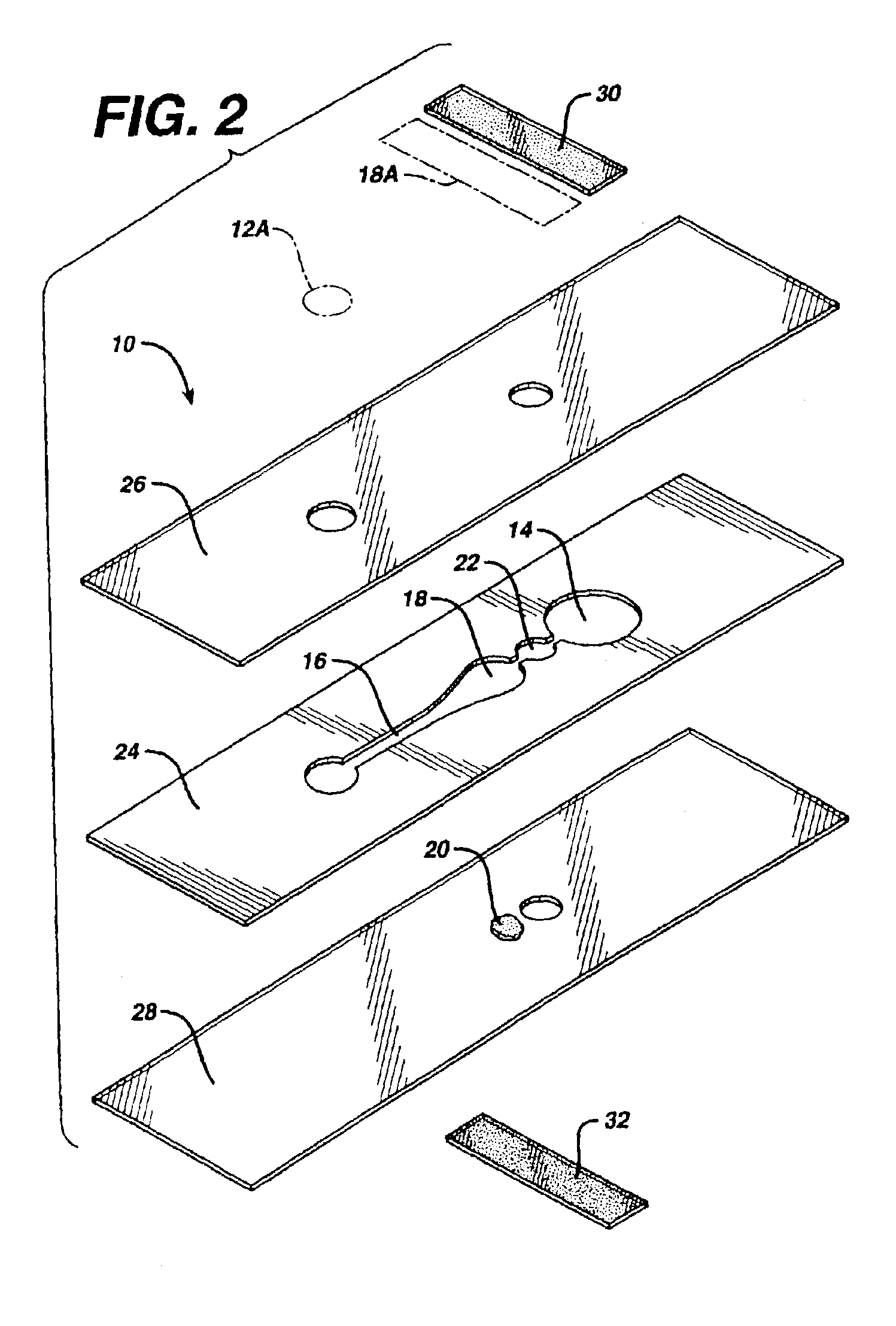
[0083]A strip of this invention is made by first passing a double-sided adhesive tape (RX 675SLT, available from Scapa Tapes, Windsor, Conn.) sandwiched between two release liners into a laminating and rotary die-cutting converting system. The pattern shown in FIG. 6, with the exception of the stop junction, is cut through the top release liner and tape, but not through the bottom release liner, which is then removed as waste, along with the cutouts from the tape. Polyester film treated to be hydrophilic (3M9962, available from 3M, St. Paul, Minn.) is laminated to the exposed bottom side of the tape. Reagent (thromboplastin, available from Ortho Clinical Diagnostics, Raritan, N.J.) is then printed onto the reagent area (18) of the polyester film by bubble jet printing, using printing heads 51612A, from Hewlett Packard, Corvallis, Oreg. A sample port is cut in untreated polyester film (AR1235, available from Adhesives Research, Glen Rock, Pa.) and then laminated, in register, to the ...

example 2

[0084]A procedure that is similar to the one described in Example 1 is followed to make a strip of the type depicted in FIG. 10. Reagent that is bubble-jet printed onto areas 118P, 218P, and 318P is, respectively, thromboplastin; thromboplastin, bovine eluate, and recombinant Factor VIIa; and thromboplastin and bovine eluate alone. The bovine eluate (plasma barium citrate bovine eluate) is available from Haemotologic Technologies, Burlington, Vt.; and recombinant Factor VIIa from American Diagnostica, Greenwich, Conn.

[0085]Measurements made on a whole blood sample using the strip of this Example yield a curve of the type shown in FIG. 5 for each of the measurement areas. The data from the curves for the controls (measurement areas 218P and 318P) are used to qualify the data from the curve for measurement area 118P. As a result, the PT time can be determined more reliably than can be done with a strip having a single measurement area.

example 3

[0086]The device of FIGS. 12 and 13 is formed by sandwiching middle layer 124 between top layer 126 and bottom layer 128. The middle and bottom layers are injection molded polycarbonate (Lexan*121) and have thicknesses of 6.3 mm and 1.5 mm, respectively. Top layer 126 is made by die cutting 0.18 mm Lexan*8010 sheet. The elements are ultrasonically welded after the reagent of Example 1 is applied to reagent area 118. The Lexan*material is available from General Electric, Pittsfield, Mass.


PUM

PropertyMeasurementUnit
wavelengthaaaaaaaaaa
thicknessaaaaaaaaaa
thicknessaaaaaaaaaa

Abstract

A fluidic medical diagnostic device permits measurement of analyte concentration or a property of a biological fluid, particularly the coagulation time of blood. The device has at one end a sample port for introducing a sample and at the other end a bladder for drawing the sample to a measurement area. A channel carries the sample from the sample port to the measurement area, and a stop junction, between the measurement area and bladder, halts the sample flow. The desired measurement can be made by placing the device into a meter which measures a physical property of the sample—typically, optical transmittance—after it has interacted with a reagent in the measurement area.

Description

CROSS-REFERENCE[0001]This application is a continuation of U.S. patent application Ser. No. 09 / 333,765, filed Jun. 15, 1999, now U.S. Pat. No. 6,521,182 which claims benefit from U.S. Provisional Patent Application Ser. No. 60 / 093,421, filed Jul. 20, 1998, which applications are incorporated herein by reference in their entirety.BACKGROUND OF THE INVENTION[0002]1. Field of the Invention[0003]This invention relates to a fluidic medical diagnostic device for measuring the concentration of an analyte in or a property of a biological fluid.[0004]2. Description of the Related Art[0005]A variety of medical diagnostic procedures involve tests on biological fluids, such as blood, urine, or saliva, and are based on a change in a physical characteristic of such a fluid or an element of the fluid, such as blood serum. The characteristic can be an electrical, magnetic, fluidic, or optical property. When an optical property is monitored, these procedures may make use of a transparent or transluc...

Claims


Application Information

Patent Timeline
Patent Type & Authority Patents(United States)
IPC IPC(8): G01N33/48A61B5/00B01L3/00G01N33/49G01N33/52G01N33/53G01N33/543G01N33/558G01N33/86
CPCB01L3/5027B01L3/502738G01N33/4905G01N33/525G01N33/5304G01N33/54386G01N33/558Y10T436/112499B01L2200/0621B01L2200/12B01L2300/0681B01L2300/0822B01L2300/0825B01L2300/0864B01L2300/087B01L2300/0887B01L2400/0406B01L2400/0481B01L2400/0688G01N21/8483G01N2333/7454G01N2333/96447Y10T436/25375B01L3/502723A61B5/00G01N33/54388
Inventor LEMKE, JOHNSHARTLE, ROBERT JUSTICEPAN, VICTORCIZDZIEL, PHILIP
Owner LIFESCAN IP HLDG LLC
Why Eureka
Try Eureka