
Production process for catalyst

Active Publication Date: 2006-04-04
NIPPON SHOKUBAI CO LTD
View PDF27 Cites 17 Cited by
  • Summary
  • Abstract
  • Description
  • Claims
  • Application Information

AI Technical Summary

Benefits of technology

[0141]In the present invention production process for the catalyst, because the treatment container as charged with the carrier and the catalyst precursor is revolved and at the same time rocked, the supporting of the catalytic component onto the carrier can efficiently and uniformly be carried out, and the yield and the strength of the catalyst can be raised, and the dispersion in particle diameter can be reduced.
[0142]Specific techniques corresponding to examples of some preferred embodiments of the present invention and comparative examples not according to the present invention were carried out, and then their performances were evaluated. In the following description, the unit “part(s)” denotes part(s) by mass.
[0143]Hereinafter taken up as specific examples of the catalyst are as follows: a catalyst as used in the case of the production of acrylic acid by the gas phase oxidation of acrolein, a catalyst as used in the ca

Problems solved by technology

As to the aforementioned conventional process for supporting the catalytic component onto the carrier by the stir-mixing, there are problems such that: the supporting ratio is low, and the production yield of the objective catalyst is low, and the physical strength of the supported catalyst is low.
As to the aforementioned apparatus carrying out the stir-mixing simply by revolving the treatment container (e.g. revolving-dish type apparatus and revolving-cylinder type apparatus), the stirring efficiency of the carrier and the catalyst precursor is not very good, and therefore, the ununiformity in the adhesion of the catalyst precursor to the carrier takes place, so that the dispersion occurs to the particle diameters of the catalyst as obtained by the supporting treatment.
As a result, there are the problems such that: the production yield of the catalyst is low, and the physical strength of the catalyst is also low.
As to the fluidized-bed granulation apparatus, the resultant catalysts (particulate catalysts) violently collide with each other due to the gas stream, and therefore the catalytic component is easily peeled off.
Usually in the production of the catalyst, even if the carrier and the catalyst precursor are strongly stirred, the supporting of the catalytic component onto the carrier does not become better.
In the case where the stirring is too strong like in such as the aforementioned fluidized-bed granulation apparatus, the catalytic component is rather not supported well.

Method used


Image

  • Production process for catalyst
  • Production process for catalyst

Examples


example 1

[0157]:

[0158]Spherical silica-alumina carrier having particle diameters of 4.5 to 5.0 mm.

[0159]:

[0160]While 20,000 parts of pure water was heat-stirred, 3,000 parts of ammonium molybdate, 663 parts of ammonium metavanadate, and 459 parts of ammonium paratungstate were dissolved therein. Separately, while 2,000 parts of pure water was heat-stirred, 855 parts of copper nitrate trihydrate was dissolved therein. The resultant two aqueous solutions were mixed together, thus obtaining a catalyst precursor in the form of a suspension.

[0161]:

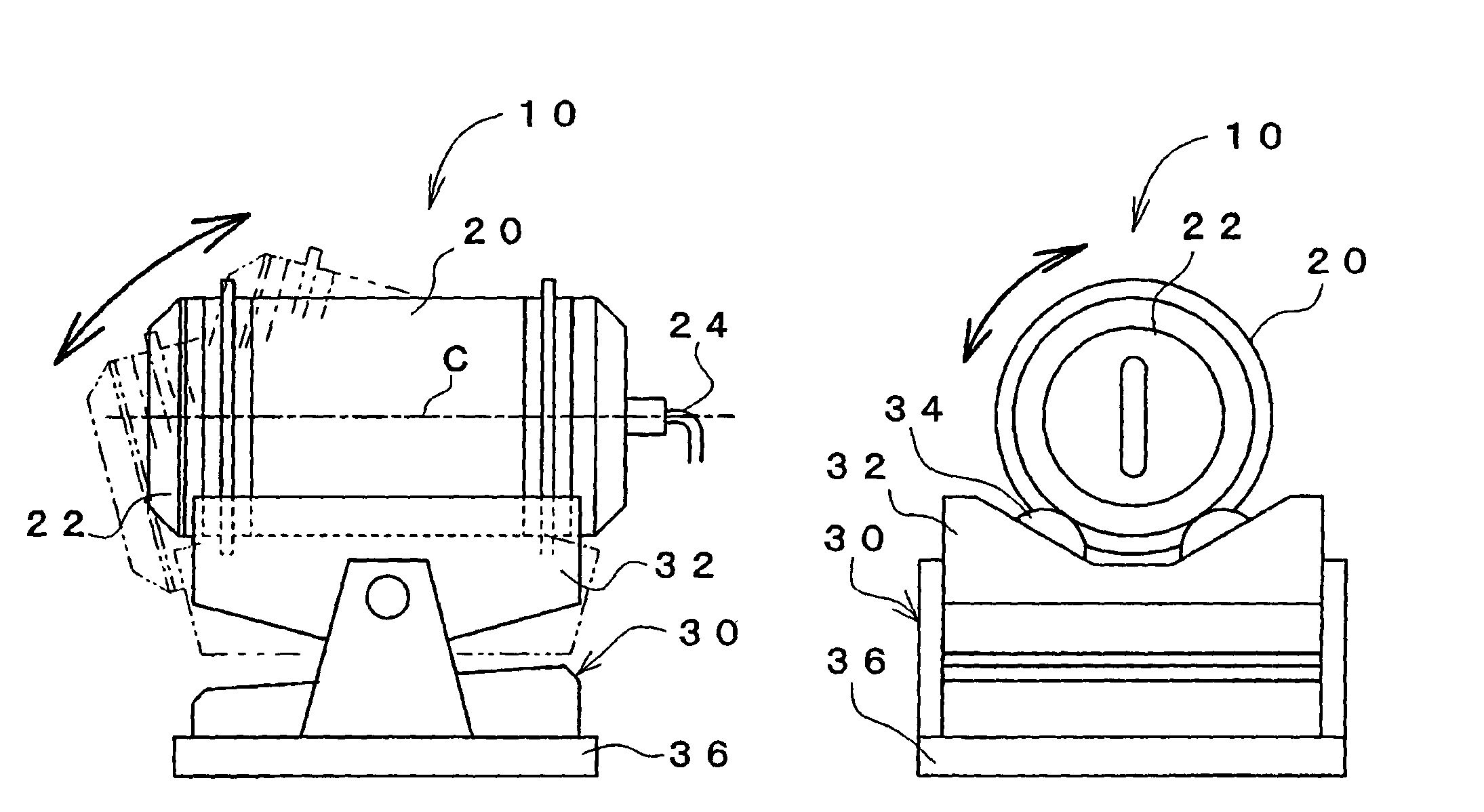
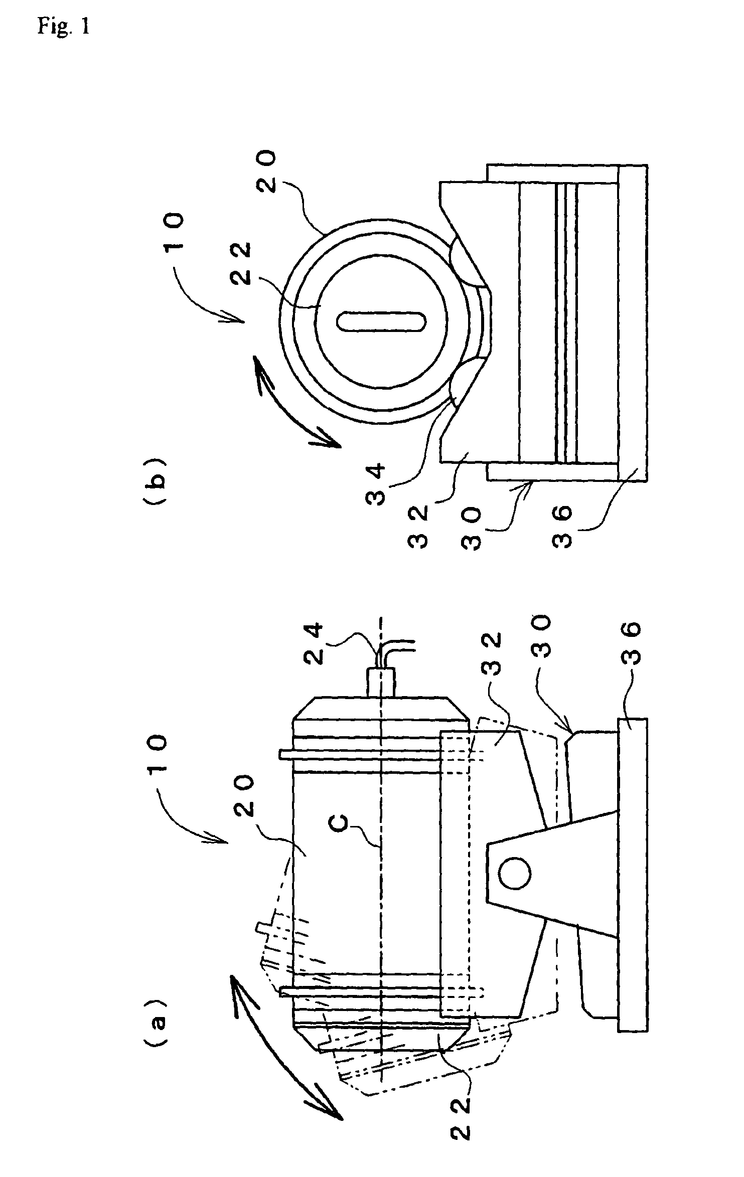
[0162]Rocking Mixer (model: RM-30) produced by Aichi Denki Co., Ltd.

[0163]An external heating unit is equipped thereto. The treatment container is roughly the shape of a cylinder of 285 mm in diameter, 540 mm in length, and about 30 dm3 in capacity.

[0164]The treatment container is equipped in a horizontal state, and then revolved around the central axis and at the same time rocked in the upward and downward directions.

[0165]:

[0166]The treatment containe...

example 2

[0172]A catalyst C was obtained in the same way as of Example 1 except that: the supporting treatment was carried out in a state where the inside of the treatment container was put under a reduced pressure of 100 hPa by connecting a vacuum pump to the exhaust piping which opened into the treatment container, It took 220 minutes to finish spraying the entirety of the predetermined amount of the suspension. Between the exhaust piping and the vacuum pump, there was set a trap for preventing such as water vapor (discharged from the treatment container) from flowing into the vacuum pump.

example 3

[0173]:

[0174]Spherical silica-alumina carrier having particle diameters of 4.5 to 5.0 mm.

[0175]:

[0176]A suspension as obtained by the same process as of the catalyst precursor of Example 1 was dried with a drum dryer and thereafter calcined at 400° C. under air atmosphere over a period of 6 hours. The resultant calcined product was pulverized so as to have particle diameters of not larger than 500 μm, thus obtaining a powdery catalyst precursor.

[0177]:

[0178]The treatment container of the same supporting treatment apparatus as of Example 1 was charged with 6 dm3 of the carrier.

[0179]While the treatment container was revolved at a revolution rate of 15 rpm, the treatment container was rocked at 5 spm in a rocking angle of 40°. While the revolution and the rocking were continued, pure water to be a binder was sprayed into the treatment container from the spray nozzle. After the treatment had been carried out for 10 minutes, the revolution and rocking of the treatment container were onc...


PUM

PropertyMeasurementUnit
Temperatureaaaaaaaaaa
Fractionaaaaaaaaaa
Angular velocityaaaaaaaaaa

Abstract

There is disclosed a production process for a catalyst which process makes it possible to efficiently carry out the supporting of a catalytic component onto a carrier and to obtain the catalyst excellent in quality and performance. This production process is a production process for the catalyst including a particulate lump carrier and a catalytic component supported thereon; with the production process comprising the step of carrying out simultaneous revolution and rocking of a treatment container 20 as charged with the carrier and a catalyst precursor including the catalytic component, thereby supporting the catalytic component onto the carrier.

Description

[0001]This is a continuation-in-part of U.S. patent application Ser. No. 10 / 615,435 filed Jul. 8, 2003 abandoned and claims the benefit thereof under 35 U.S.C. § 120.BACKGROUND OF THE INVENTION[0002]A. Technical Field[0003]The present invention relates to a production process for a catalyst. More particularly, the present invention is intended for the production process for a catalyst which is utilized for various chemical reactions (e.g. reforming, cracking, (amm)oxidation, and reduction of hydrocarbons) in the form such that a catalytic component (e.g. metal elements) is supported on a carrier.[0004]B. Background Art[0005]Catalysts in the form such that a catalytic component is supported on a particulate lump carrier (such catalysts may hereinafter be referred to simply as “supported catalysts”) can efficiently be brought into contact with a liquid or gaseous substance as a reactant or are easy to handle. Therefore, such catalysts are widely utilized as catalysts for production of...

Claims


Application Information

Patent Timeline
IPC IPC(8): B01J23/00B01J20/00B01J21/00B01J23/888B01J37/02B01J37/04
CPCB01J23/8885B01J37/04B01J37/0236B01J37/0223
Inventor YUNOKI, HIROMITANIMOTO, MICHIONAKAMURA, DAISUKE
Owner NIPPON SHOKUBAI CO LTD
Features
  • Generate Ideas
  • Intellectual Property
  • Life Sciences
  • Materials
  • Tech Scout
  • Unparalleled Data Quality
  • Higher Quality Content
  • 60% Fewer Hallucinations
Learn More