Silicon microphone

a microphone and silicon technology, applied in the field of silicon microphones, can solve the problems of reducing the mechanical compliance of the microphone diaphragm, affecting the performance of the microphone, so as to achieve the effect of reducing the parasitic capacitan

Inactive Publication Date: 2006-04-04
KNOWLES ELECTRONICS INC
View PDF30 Cites 80 Cited by
  • Summary
  • Abstract
  • Description
  • Claims
  • Application Information

AI Technical Summary

Benefits of technology

[0013]In order to simplify the fabrication process it is necessary to combine the functionality of some of the mechanical structures. According to the invention, a diaphragm anchoring scheme is provided which renders the diaphragm essentially free, i.e., the film stress is relieved and yet, the entire diaphragm is anchored in place on the substrate. This diaphragm design can be used for fabricating MEMS microphones with characteristic acoustic sensitivity that is relatively insensitive to the (diaphragm) residual film stress. In this design, the insensitivity of the diaphragm's compliance to residual film stress is achieved through the special anchoring scheme. Since the diaphragm is physically anchored or attached to the support substrate, no additional structure is required to contain the diaphragm. Hence the fabrication method is simpler than the free plate design described in the previous section.
[0020]It is still further contemplated that the transducer includes a back plate, that the back plate is smaller than the diaphragm and the center of the back plate is aligned with the center of the diaphragm to minimize parasitic capacitance.

Problems solved by technology

One major difficulty often encountered in micromachining is the control of film stress.
Tensile stress severely decreases the mechanical compliance of a microphone diaphragm.
In these situations, there is insufficient constraints to keep the free plate diaphragm from being pulled away from the substrate and being damaged during processing or when handling a completed device.

Method used


Image

  • Silicon microphone
  • Silicon microphone
  • Silicon microphone

Examples


Embodiment Construction

[0025]While this invention is susceptible of embodiment in many different forms, there is shown in the drawings and will herein be described in detail a preferred embodiment of the invention with the understanding that the present disclosure is to be considered as an exemplification of the principles of the invention and is not intended to limit the broad aspect of the invention to the embodiment illustrated.

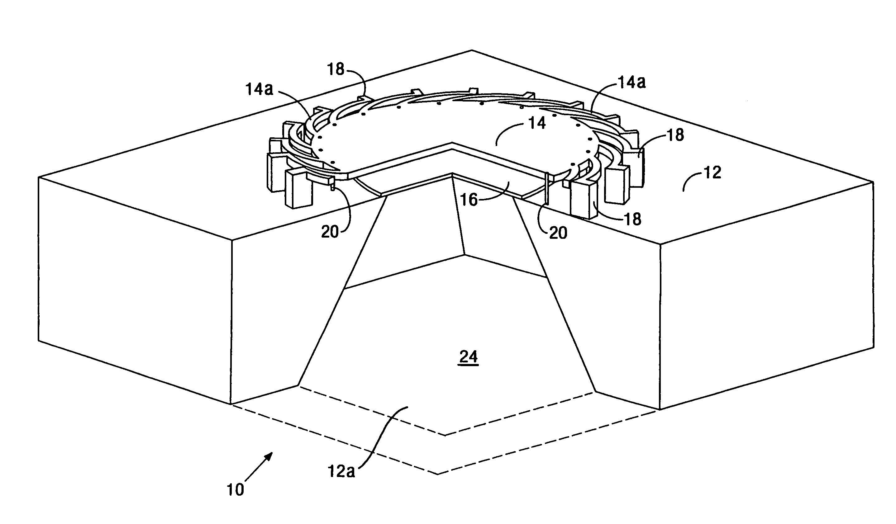
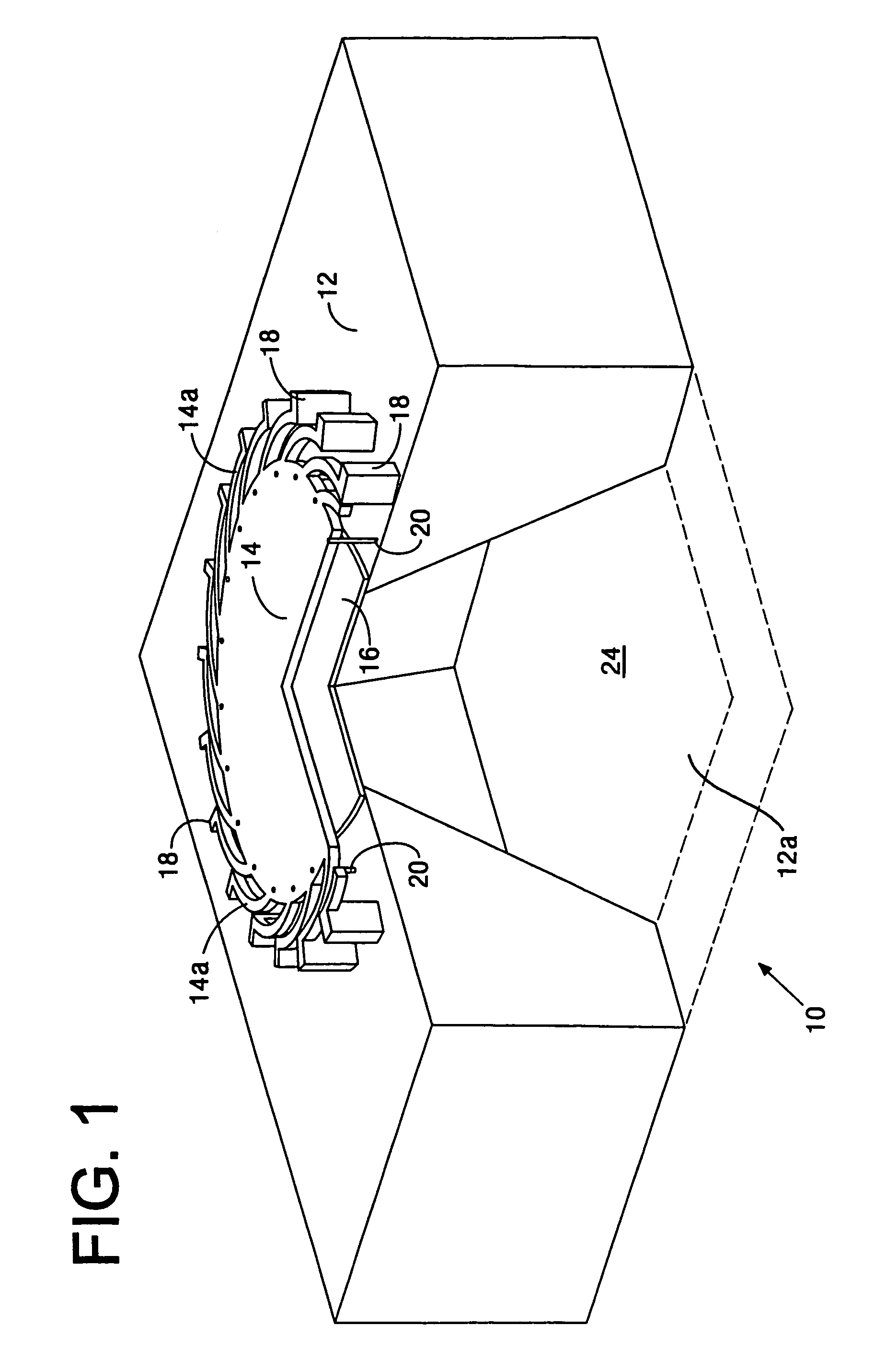
[0026]A solid-state transducer 10 according to the invention is illustrated in FIG. 1. In the present description, the transducer 10 is shown as a condenser microphone. However, the transducer could be other devices, such as a pressure sensor or an accelerometer. The transducer 10 comprises a semi-conductor substrate 12 forming a support structure and having an opening 12a. The transducer 10 further includes a thin-film structure forming a diaphragm 14 responsive to fluid-transmitted acoustic pressure. The diaphragm 14 is disposed over the opening 12a. The diaphragm 14 includes ...


PUM


Abstract

A solid-state transducer is disclosed. The transducer comprises a semi-conductor substrate forming a support structure and having an opening. A thin-film structure forming a diaphragm responsive to fluid-transmitted acoustic pressure is disposed over the opening. The transducer further includes a plurality of semi-conductor supports and tangential arms extending from the diaphragm edge for connecting the periphery of the diaphragm to the supports. The tangential arms permit the diaphragm to rotate relative to the supports to relieve film stress in the diaphragm. The transducer still further includes a plurality of stop bumps disposed between the substrate and the diaphragm. The stop bumps determine the separation of the diaphragm from the substrate when the transducer is biased.

Description

CROSS-REFERENCE TO RELATED APPLICATIONS[0001]Not applicable.FEDERALLY SPONSORED RESEARCH OR DEVELOPMENT[0002]Not applicable.TECHNICAL FIELD[0003]The present invention relates to silicon microphones, and more particularly, to a silicon microphone having a diaphragm with reduced residual stress.BACKGROUND OF THE INVENTION[0004]Micro-electromechanical systems (MEMS) technology allows the manufacture of small (microns to hundreds of micron) electromechanical components using the precision manufacturing techniques of microelectronics. The term often used to describe MEMS manufacturing process is micromachining. Prime examples of MEMS devices on the market include pressure sensors and accelerometers. See L. Sprangler and C. J. Kemp, ISAAC-integrated silicon automotive accelerometer, in Tech. Dig. 8th Int. Conf. On Solid-State Sensors and Actuators (Transducers '95), Stockholm, June 1995, pp. 585–588. See also W. S. Czarnocki and J. P. Schuster. 1995. “Robust, Modular, Integrated Pressure ...

Claims


Application Information

Patent Timeline
Patent Type & Authority Patents(United States)
IPC IPC(8): H01L29/82H04R7/18H04R19/00H04R19/04
CPCB81B3/0072H04R19/005B81B2203/0127B81B2201/0257H04R1/02H04R19/02
Inventor LEE, SUNG BOKLOEPPERT, PETER V.
Owner KNOWLES ELECTRONICS INC
Why Eureka
Try Eureka