Method for manufacturing magnetic sensor, magnet array used in the method, and method for manufacturing the magnet array

a technology of magnetic sensor and manufacturing method, which is applied in the direction of magnets, magnet bodies, instruments, etc., can solve the problems of difficult mass production of small biaxial magnetic sensors using synthetic spin valve films, and difficult generation of such magnetic fields

Inactive Publication Date: 2006-04-04
YAMAHA CORP
View PDF20 Cites 17 Cited by
  • Summary
  • Abstract
  • Description
  • Claims
  • Application Information

AI Technical Summary

Benefits of technology

[0009]An object of the present invention is to provide a method for manufacturing a magnetic sensor which enables mass production of small-sized biaxial magnetic sensors using a synthetic spin valve film, a magnet array suited for use in the method, and a method for manufacturing the magnet array.
[0031]As mentioned previously, mutually orthogonal, very strong magnetic fields are generated at the adjacent rectangular portions of the yoke of the magnet array and at portions in the vicinity of (immediately above) the rectangular portions. Accordingly, the strong magnetic fields are applied to two adjacent element films, so that magnetization of the pinned layers of the synthetic spin valve films of the element films can be reliably pinned. Also, there can be formed a biaxial magnetic sensor in which at least two GMR elements are disposed very close to each other on the same substrate and in which magnetization directions of pinned layers of synthetic spin valve films of the GMR elements are perpendicular to each other. Furthermore, by use of the above-described magnet array, pinning of magnetization can be performed simultaneously (in the same heat treatment process) with respect to pinned layers of a plurality of element films formed on a single wafer so as to yield two or more (a large number of) biaxial magnetic sensors. Thus, a biaxial magnetic sensor can be manufactured at low cost.
[0033]The positions where the openings are formed are where lines of magnetic force extending (or generating) from magnetic poles of permanent magnets intersect, with resultant instability in magnetic fields. Forming the openings at such positions prevents intersection of lines of magnetic force, thereby eliminating instability in magnetic fields. Thus, a stable, strong, uniform magnetic field can be locally generated in each of the rectangular portions of the yoke. As a result, use of the magnet array allows, for example, effective pinning of magnetization for the film that is to become the fixed layer, and effective magnetization of a bias magnet film of a magnetic sensor.

Problems solved by technology

However, generation of such magnetic fields is very difficult.
As a result, a small-sized biaxial magnetic sensor using a synthetic spin valve film has encountered difficulty in mass production.

Method used


Image

  • Method for manufacturing magnetic sensor, magnet array used in the method, and method for manufacturing the magnet array
  • Method for manufacturing magnetic sensor, magnet array used in the method, and method for manufacturing the magnet array
  • Method for manufacturing magnetic sensor, magnet array used in the method, and method for manufacturing the magnet array

Examples


Embodiment Construction

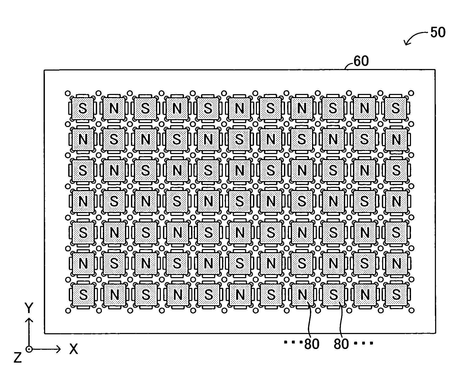
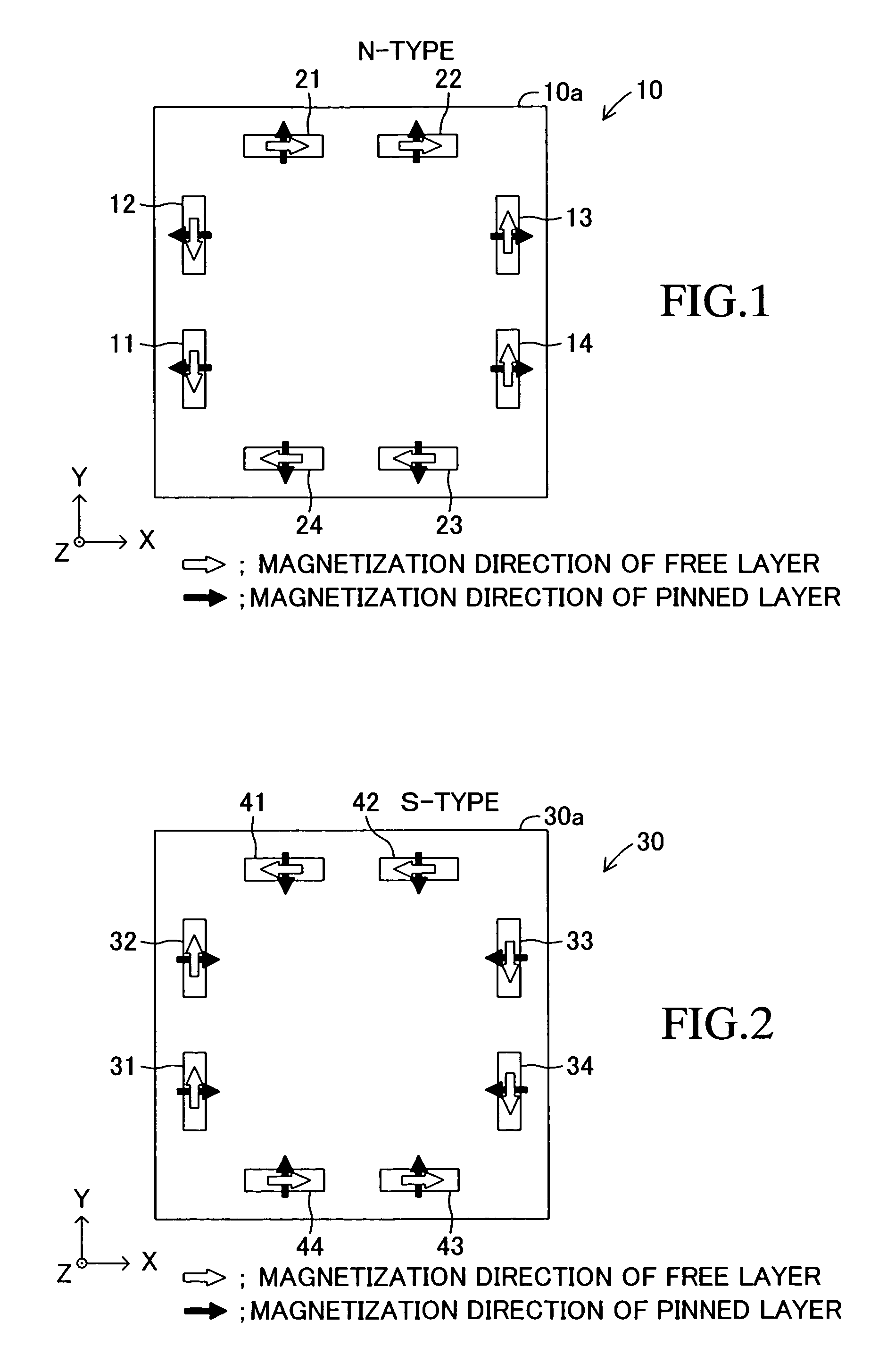
[0093]Embodiments of the present invention will next be described in detail with reference to the drawings. An embodiment of a magnetic sensor according to the present invention will be first described. The magnetic sensor is classified into an N-type magnetic sensor 10 shown in FIG. 1 and an S-type magnetic sensor 30 shown in FIG. 2. The N-type and S-type magnetic sensors 10 and 30 are manufactured by manufacturing methods to be described later.

[0094]The N-type magnetic sensor 10 and the S-type magnetic sensor 30 assume substantially the same shape and configuration except for the fixed magnetization direction of a pinned layer as represented by the black solid arrow of FIGS. 1 and 2 and the magnetization direction of a free layer in an initial state (a state in which an external magnetic field is absent) as represented by the inline arrow of FIGS. 1 and 2. Therefore, the N-type magnetic sensor 10 will be mainly discussed below.

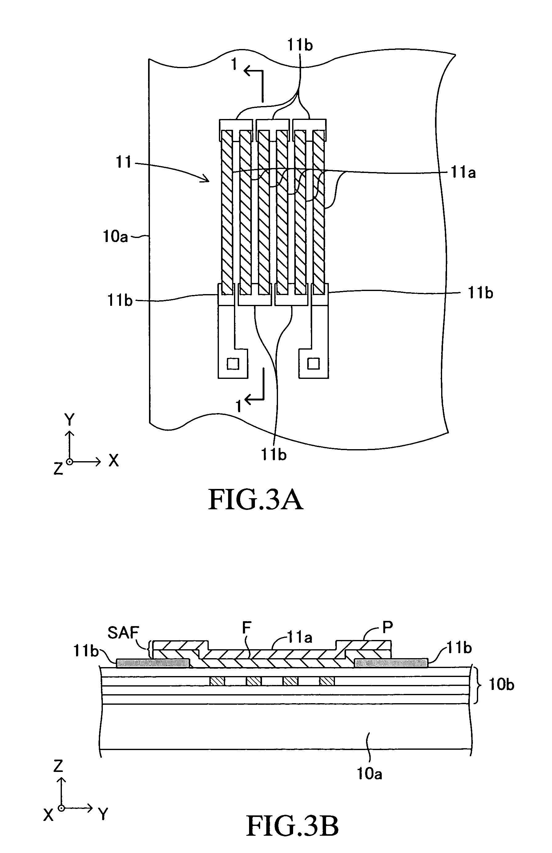
[0095]As shown in FIG. 1, the magnetic sensor 10 inclu...


PUM

PropertyMeasurementUnit
thicknessaaaaaaaaaa
thicknessaaaaaaaaaa
thicknessaaaaaaaaaa

Abstract

A magnetic sensor includes eight SAF-type GMR elements. Four of the GMR elements detect a magnetic field in the direction of the X-axis and are bridge-connected to thereby constitute an X-axis magnetic sensor. The other four GMR elements detect a magnetic field in the direction of the Y-axis and are bridge-connected to thereby constitute a Y-axis magnetic sensor. The magnetization of a pinned layer of each of the GMR elements is pinned in a fixed direction by means of a magnetic field that a permanent bar magnet inserted into a square portion of a yoke of a magnet array generates in the vicinity of a rectangular portion of the yoke. A magnetic field generated in the vicinity of a certain rectangular portion of the yoke differs in direction by 90 degrees from a magnetic field generated in the vicinity of a rectangular portion adjacent to the former rectangular portion.

Description

BACKGROUND OF THE INVENTION[0001]1. Field of the Invention[0002]The present invention relates to a method for manufacturing a magnetic sensor using a magnetoresistance element (so-called synthetic spin valve film) having a multifilm laminated fixed layer, to a magnet array suited for use in the method, and to a method for manufacturing the magnet array.[0003]2. Description of the Related Art[0004]A conventionally known giant magnetoresistance element (hereinafter referred to as a “GMR element”) includes a fixed layer that includes a pinned layer, and a pinning layer for pinning the magnetization of the pinned layer in a fixed direction; a free layer whose magnetization direction varies in accordance with an external magnetic field; and a spacer layer disposed between the pinned layer and the free layer and made of a nonmagnetic electric conductor. The resistance of the GMR element varies in accordance with the angle between the magnetization direction of the pinned layer and the mag...

Claims


Application Information

Patent Timeline
Patent Type & Authority Patents(United States)
IPC IPC(8): H01H7/02G11B5/127H01L43/02G01R33/09H01L43/00H01L43/08H01L43/12
CPCB82Y25/00G01R33/093Y10T29/49021Y10T29/49002H10N50/10
Inventor OOHASHI, TOSHIYUKIAISO, KOKICHI
Owner YAMAHA CORP
Why Eureka
Try Eureka