
Optical device, lens and optical element for focusing a laser beam and apparatus and method for assembling the optical device

a laser beam and optical element technology, applied in the field of optical devices, can solve the problems of not preventing nor altering the reading of possible optical codes, and achieve the effects of reducing the risk of altering the optics of the system, reducing the possibility of device focusing point variations, and certain elasticity and deformation

Inactive Publication Date: 2006-04-04
DATALOGIC
View PDF21 Cites 4 Cited by
  • Summary
  • Abstract
  • Description
  • Claims
  • Application Information

AI Technical Summary

Benefits of technology

[0023]Advantageously, therefore, the device of the present invention is provided with means adapted to introduce diffraction into the emission laser beam so as to control the profile of the spot for a great range of distances and obtain an increase in the depth of field of the laser beam. More advantageously, said means are directly applied on the focusing lens so as to allow a significant reduction in the overall dimensions of the focusing device and, thus, of the optical reader on which it is to be assembled. In addition, the device of the invention is especially simple from the constructive point of view, and it permits the use of widely used optical elements: this implies lower production costs.
[0049]The above described lens and optical elements are especially adapted to be assembled inside small-size and low-priced optical readers, thus allowing to obtain the above mentioned advantages.

Problems solved by technology

In fact, for a laser beam as the latter, the combined effect of focusing and diffraction produces, in the laser beam, a central portion having a greater collimation (and thus, a greater depth of field), and some side lobes which, although often undesired, do not prevent nor alter the reading of possible optical codes.

Method used


Image

  • Optical device, lens and optical element for focusing a laser beam and apparatus and method for assembling the optical device
  • Optical device, lens and optical element for focusing a laser beam and apparatus and method for assembling the optical device
  • Optical device, lens and optical element for focusing a laser beam and apparatus and method for assembling the optical device

Examples


Embodiment Construction

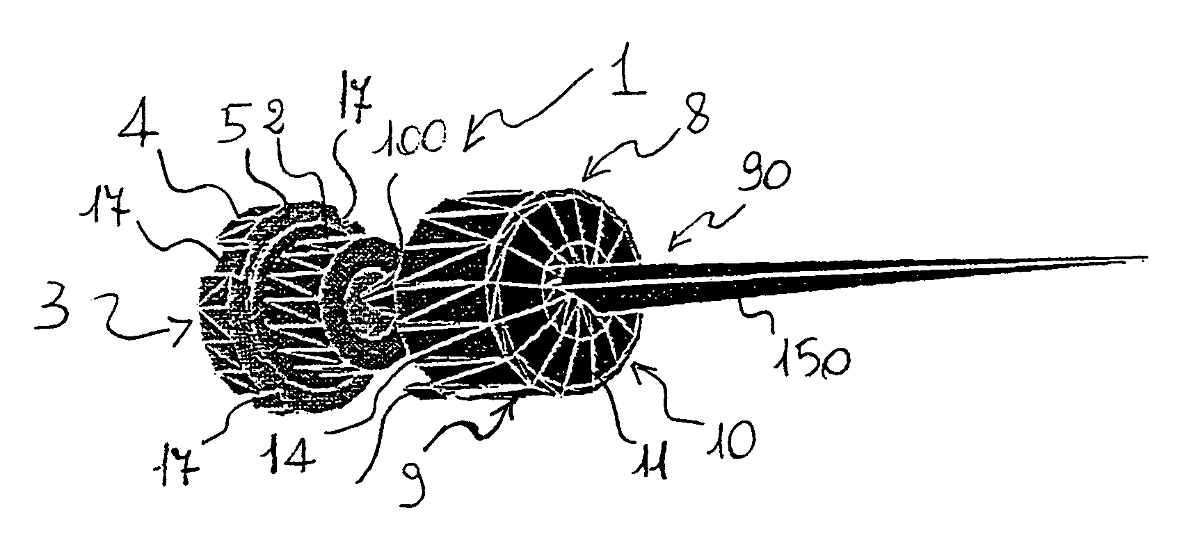
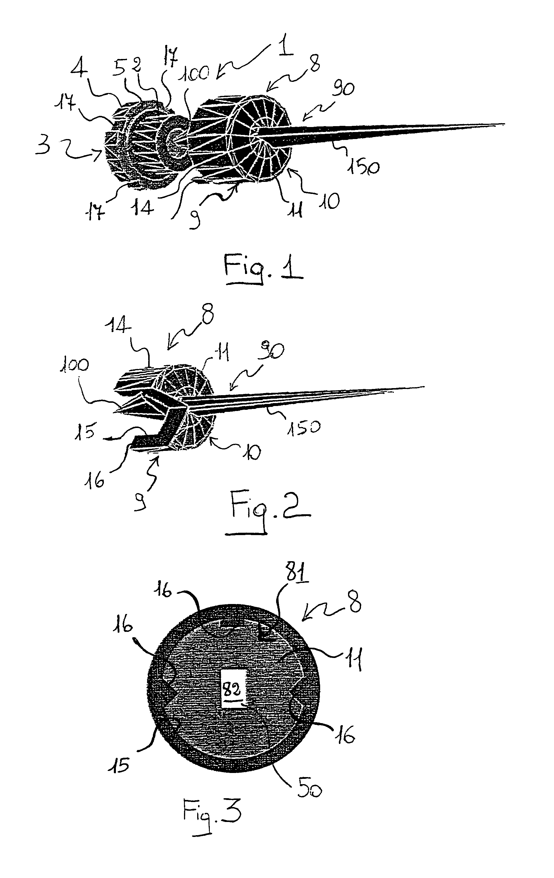
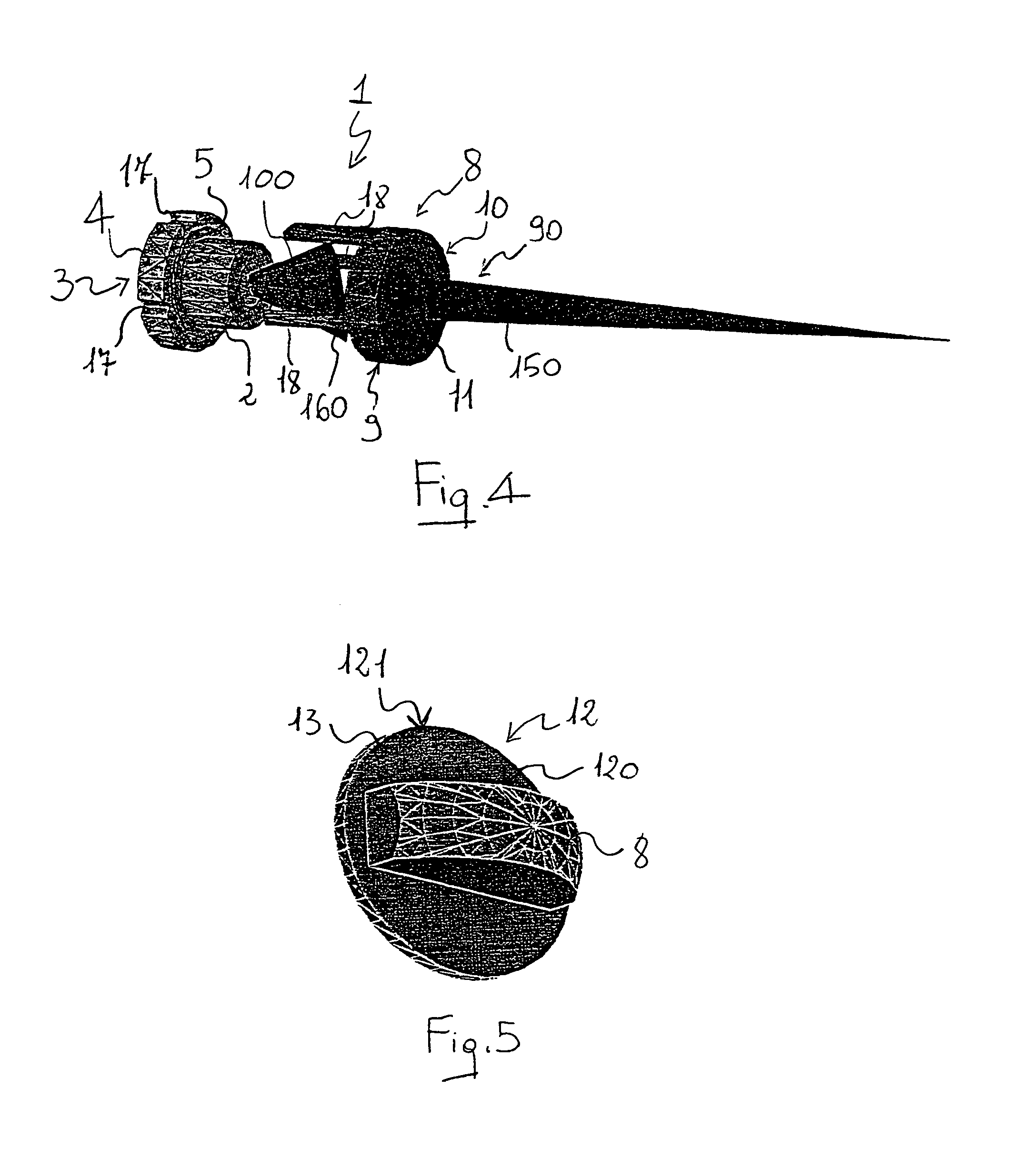
[0068]In these figures, numeral 1 refers to an optical device for focusing a laser beam, in particular a substantially elliptic and astigmatic laser beam, according to the present invention. Device 1 is adapted to be used on a small-size low-priced optical reader (for example, a portable reader of optical codes) for the purpose of increasing the depth of field of the laser beam so as to allow reading information located at different distances and / or inclinations with respect to the reader itself.

[0069]Device 1 comprises a source of emission 2, typically a conventional semiconductor laser diode, which is adapted to emit—along an optical path of emission 90—a divergent laser beam 100, astigmatic and with a substantially elliptic profile.

[0070]The laser diode 2 is housed into the device 1 by means of a support structure 3; the latter essentially comprises a substantially cylindrical body 4 which is provided, on a front surface 5, with a plurality of housings 6 adapted to house respecti...


PUM


Abstract

The invention relates to an optical device for focusing a laser beam, comprising a source of emission of a laser beam, for example a substantially elliptic and astigmatic laser beam, a focusing lens of the laser beam and first aperture adapted to select a central portion of the laser beam. The first aperture is directly applied on the focusing lens, and comprises a coating made of a substantially opaque material which are applied (for example, by spraying, sputtering, evaporation, printing, painting) on a peripheral portion of a front surface of the focusing lens so as to allow the propagation of the central portion of the laser beam and obstruct the propagation of a surrounding portion of beam. The device of the invention is extremely simple from the constructive point of view, and is inexpensive and small-sized.

Description

BACKGROUND OF THE INVENTION[0001]1. Field of the Invention[0002]The present invention relates to an optical device for focusing a laser beam, for example a substantially elliptic and astigmatic laser beam.[0003]The invention also relates to a lens and to an optical element for focusing a laser beam emitted by a source of emission, in particular a laser diode. The invention also relates to an apparatus and a method for assembling the above device.[0004]Preferably, but not exclusively, the device—or the lens, or the optical element—of the invention are adapted to be used on a small low-priced optical reader such as, for example, a portable reader of optical codes.[0005]In this description and following claims, the term “optical reader” refers to any device adapted to acquire information relating to an object (for example, distance, volume, dimensions, or its identification data) through the acquisition and the processing of a luminous signal diffused by it, while the term “optical cod...

Claims


Application Information

Patent Timeline
Patent Type & Authority Patents(United States)
IPC IPC(8): G02B17/00G02B1/10G02B5/00G02B27/62G06K7/10H01S5/00H01S5/022
CPCG02B1/10G02B5/005H01S5/02288G06K7/10702G06K7/10811G02B27/62H01S5/02253
Inventor OLIVA, GUIDO MAURIZIO
Owner DATALOGIC
Learn More