System and method for performing diagnostics on a mobile station using over-the-air transfer of interpreted byte-code program

a mobile station and byte-code technology, applied in the field of wireless networks, can solve the problems of reducing the development and maintenance costs of diagnostic software, reducing the cost of supporting a wireless handset, and reducing the cost of bringing a subscriber's handset into the service center

Inactive Publication Date: 2006-04-04
SAMSUNG ELECTRONICS CO LTD
View PDF9 Cites 54 Cited by
  • Summary
  • Abstract
  • Description
  • Claims
  • Application Information

AI Technical Summary

Benefits of technology

[0032]The present invention significantly reduces the cost of supporting a wireless handset after it is sold to a subscriber. A handset according to the principles of the present invention does not require have a built-in algorithm or method for doing diagnostics. The interpreted bytecode provides the benefit of a write-once, run-anywhere application, thereby reducing development and maintenance costs of diagnostic software. Additionally, the diagnostic program is transient and consumes no memory or resources after the diagnostic operations are performed. The diagnostic progra

Problems solved by technology

Because the bandwidth for a current generation mobile station is typically limited to a few tens of kilobits per second (Kbps), the applications for the current generation of mobile stations are relatively limited.
Detecting this is costly and time consuming for the subscriber, the service provider and/or the handset vendor.
Unfortunately, these methods have several drawbacks.
It is costly to have a subscriber bring a handset into the service center for simple diagnostic testing and repairs.
It also is expensive for the handset manufacturer to develop separate diagnostic programs fo

Method used


Image

  • System and method for performing diagnostics on a mobile station using over-the-air transfer of interpreted byte-code program
  • System and method for performing diagnostics on a mobile station using over-the-air transfer of interpreted byte-code program
  • System and method for performing diagnostics on a mobile station using over-the-air transfer of interpreted byte-code program

Examples


Embodiment Construction

[0042]FIGS. 1 through 5, discussed below, and the various embodiments used to describe the principles of the present invention in this patent document are by way of illustration only and should not be construed in any way to limit the scope of the invention. Those skilled in the art will understand that the principles of the present invention may be implemented in any suitably arranged wireless network.

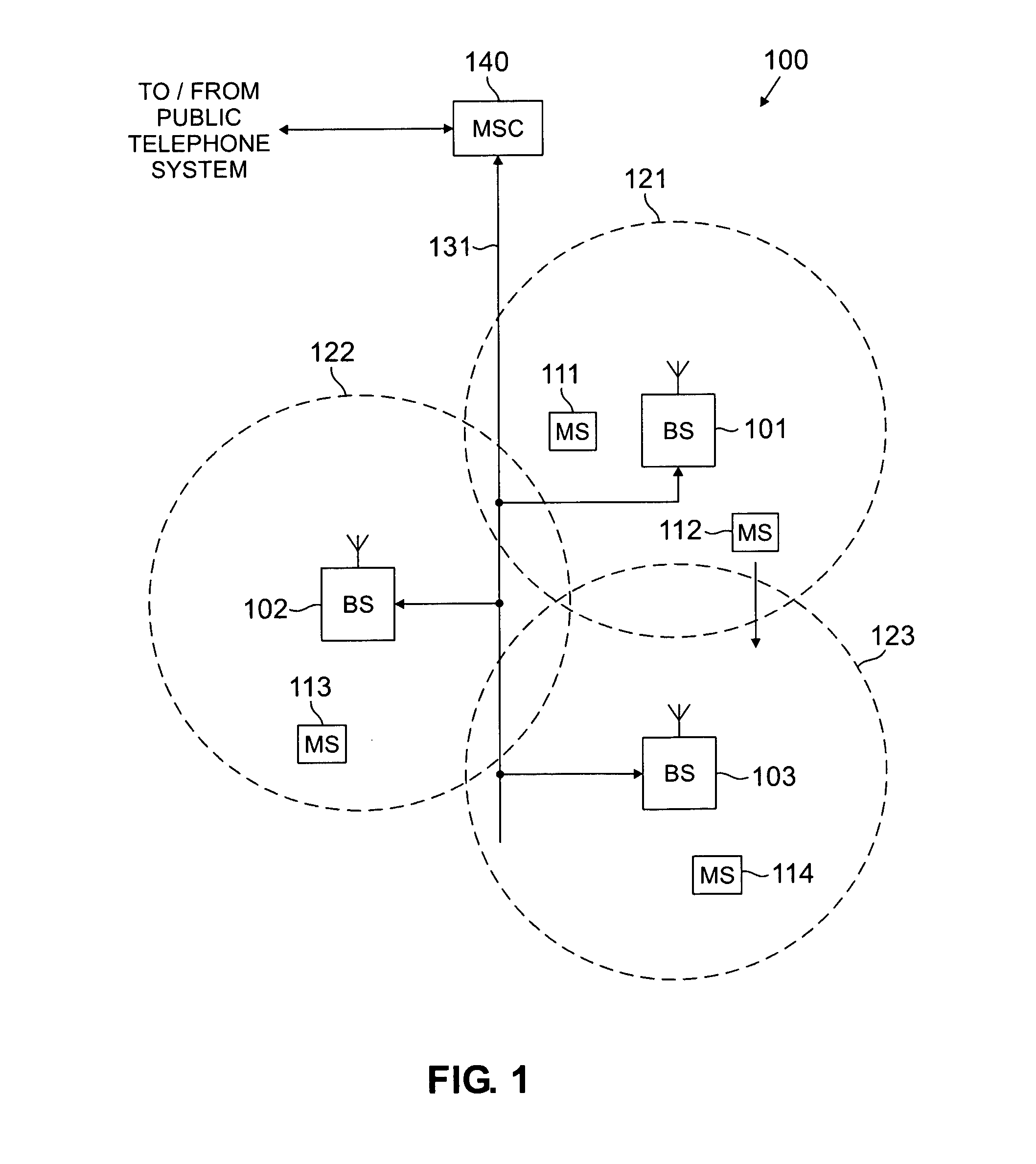
[0043]FIG. 1 illustrates a general overview of an exemplary wireless network 100 according to one embodiment of the present invention. Wireless telephone network 100 comprises a plurality of cell sites 121–123, each containing one of the base stations, BS 101, BS 102, or BS 103. Base stations 101–103 are operable to communicate with a plurality of mobile stations (MS) 111–114. Mobile stations 111–114 may be any suitable wireless communication devices, including conventional cellular telephones, PCS handset devices, portable computers, telemetry devices, and the like.

[0044]Dotted lines...


PUM


Abstract

There is disclosed a mobile station diagnostic testing system for use in a wireless network comprising a plurality of base stations capable of communicating with a plurality of mobile stations. The mobile station diagnostic testing system tests the operation of a first mobile station. The mobile station diagnostic testing system comprises: 1) a database for storing a mobile station diagnostic testing file comprising a mobile station diagnostic testing program in interpreted byte-code format; and 2) a diagnostics controller coupled to the database for receiving a notification indicating that a fault has occurred in the first mobile station. In response to receipt of the notification, the mobile diagnostics testing system retrieves the mobile station diagnostic testing file from the database and transmits it to the first mobile station. Receipt of the mobile station diagnostic testing file causes the mobile station to execute the mobile station diagnostic testing program.

Description

CROSS-REFERENCE TO RELATED APPLICATIONS[0001]The present invention is related to those disclosed in the following U.S. patent applications:[0002]1. Ser. No. 09 / 500,499, filed Feb. 9, 2000, entitled “SYSTEM AND METHOD FOR SECURE OVER-THE-AIR PROVISIONING OF A MOBILE STATION FROM A PROVISIONING SERVER VIA A TRAFFIC CHANNEL;”[0003]2. Ser. No. 09 / 501,468, filed Feb. 9, 2000, entitled “SYSTEM AND METHOD FOR SECURE PROVISIONING OF A MOBILE STATION FROM A PROVISIONING SERVER USING IWF-BASED IP ADDRESS TRANSLATION;”[0004]3. Ser. No. 09 / 475,602, filed on Dec. 30, 1999, entitled “SYSTEM AND METHOD FOR SECURE PROVISIONING OF A MOBILE STATION FROM A PROVISIONING SERVER USING IP ADDRESS TRANSLATION AT THE BTS / BSC;”[0005]4. Ser. No. 09 / 475,760, filed on Dec. 30, 1999, entitled “SYSTEM AND METHOD FOR SECURE PROVISIONING OF A MOBILE STATION FROM A PROVISIONING SERVER USING E NCRYPTION;” and[0006]5. Ser. No. 09 / 542,632, filed on Apr. 4, 2000, entitled “SYSTEM AND METHOD FOR PROVISIONING OR UPDATING ...

Claims


Application Information

Patent Timeline
IPC IPC(8): H04Q7/20H04B17/00H04W24/00
CPCH04W24/00H04W24/10
Inventor MOLES, BRYAN J.HERLE, SUDHINDRA P.WEBB, RONALD J.
Owner SAMSUNG ELECTRONICS CO LTD
Why Eureka
Try Eureka