Electromagnetic acoustic transducers

a technology of acoustic transducers and emat transducers, applied in the direction of electromagnets, ultrasonic/sonic/infrasonic wave generation, and analysis of solids using sonic/ultrasonic/infrasonic waves, etc., can solve the problems of affecting the design of the transducer, and affecting the performance of the transducer. achieve the effect of more flexibility

Inactive Publication Date: 2006-04-11
PII LIMITED
View PDF8 Cites 24 Cited by
  • Summary
  • Abstract
  • Description
  • Claims
  • Application Information

AI Technical Summary

Benefits of technology

[0010]It would be desirable to be able to provide an EMAT the construction of which is such as to provide significantly more flexibility in the design of the transducer, and which allows the transducer to be used in a wider range of operating environments than heretofore.
[0013]Such separation of the two components has a very large effect on the possibilities of transducer design. In some specific applications, for example pipe inspection, a variety of technical and commercial advantages are achieved. Furthermore, barkhausen noise is eliminated.

Problems solved by technology

For the ultrasonic testing of some materials, it is impractical, or in some cases disadvantageous, to introduce a coupling medium, for example during the inspection of gas pipelines by a moving inspection vehicle, commonly referred to as an inspection pig.
Nearly all EMAT transducers suffer from ‘barkhausen’ noise when moved over the surface of a ferromagnetic system.
Barkhausen noise can be a severe problem for EMAT pipe inspection using pigs, because the inspection is carried out at speed.
There are a variety of compromises made in the design of any EMAT, but the arrangement of the magnetic field components and the electrical windings can only be manipulated within limits set by the fundamental physical method of their operation.
These are practical choices that are constrained by the operating environment, and often limit the acoustic performance of the transducer as measured by, for example, the acoustic output amplitude or the prominence of the barkhausen noise.
The design problem is therefore strongly affected by the fundamental method of the EMAT operation, which in some environments may preclude any practical solution.

Method used


Image

  • Electromagnetic acoustic transducers
  • Electromagnetic acoustic transducers
  • Electromagnetic acoustic transducers

Examples


Embodiment Construction

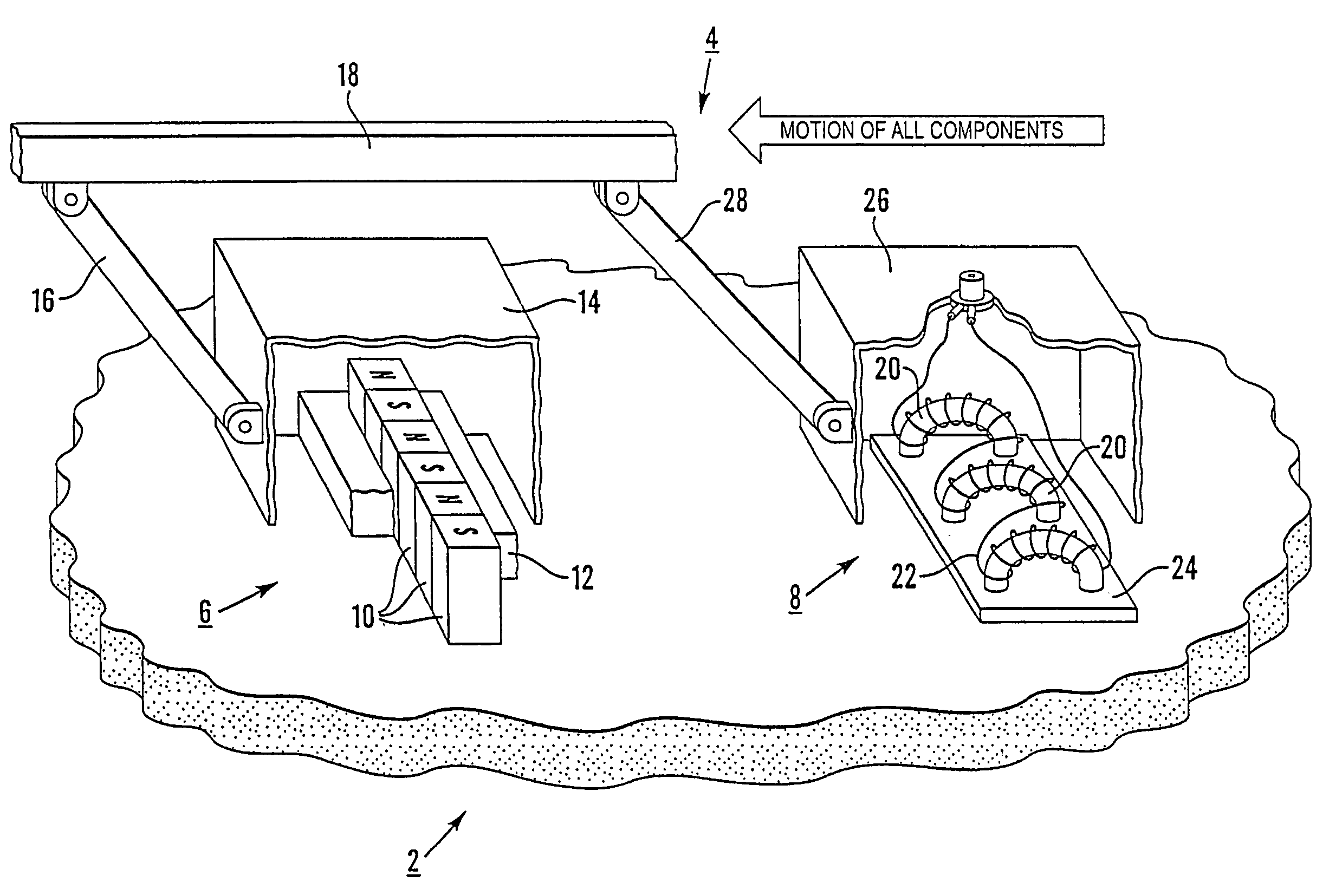
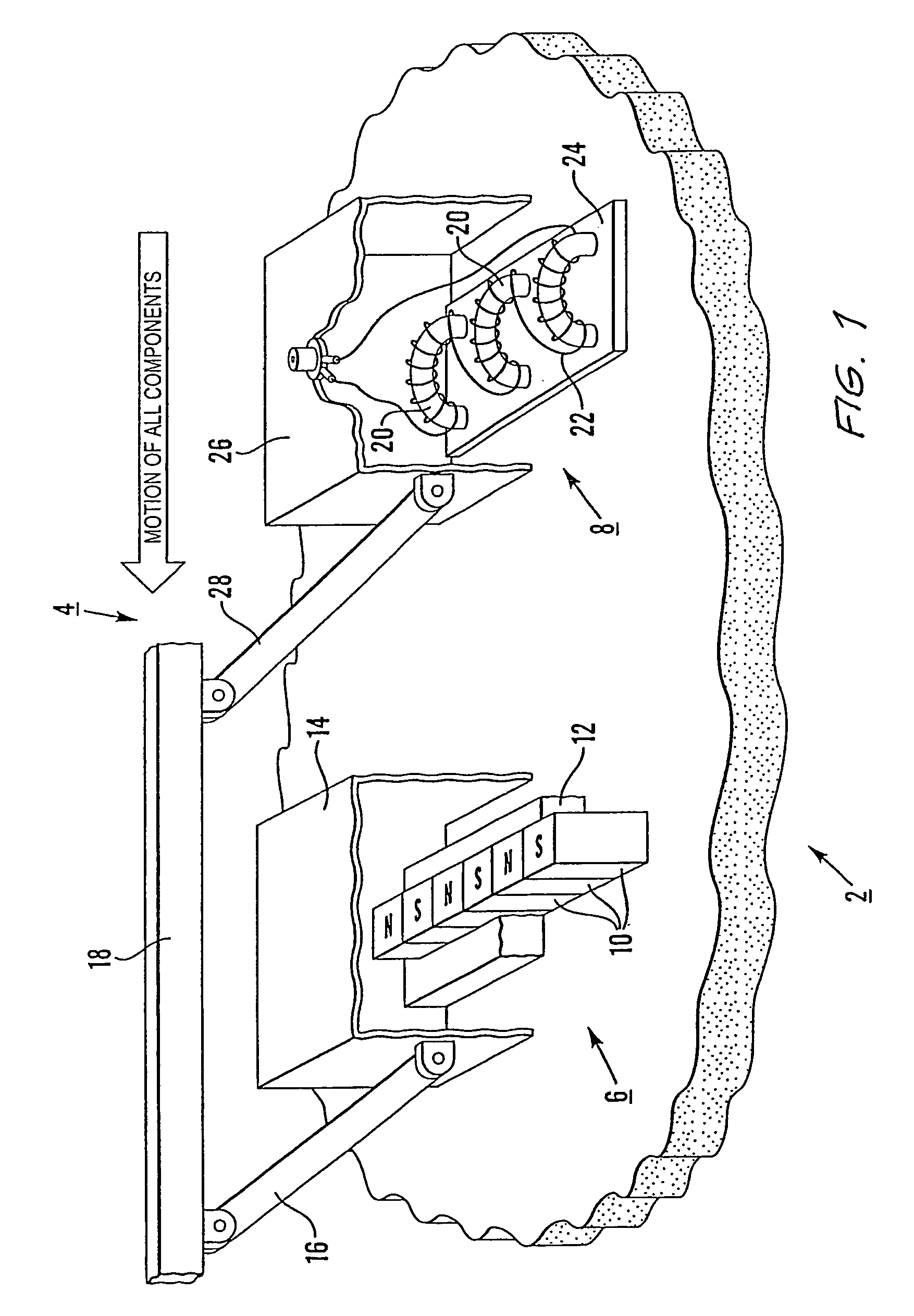
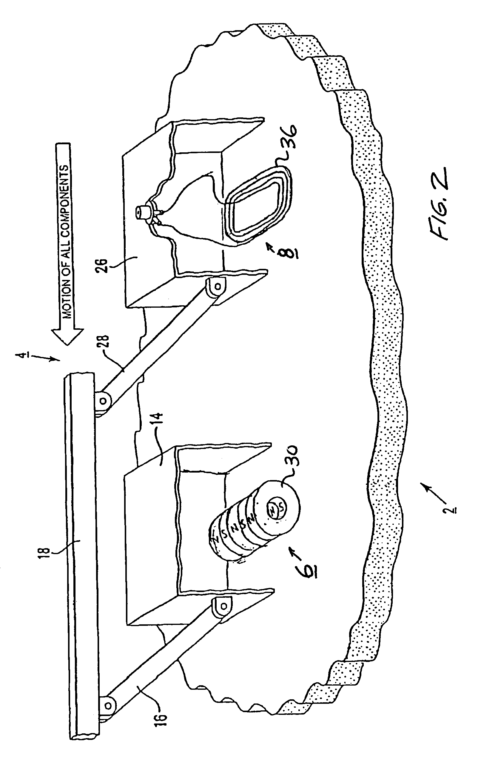
[0020]Referring to FIG. 1, a ferromagnetic material under test, which may be, for example, a high pressure steel gas pipeline, is indicated generally at 2, and an EMAT according to the invention is indicated generally at 4 for generating horizontally polarised guided shear waves.

[0021]The EMAT comprises two distinct and separate components, namely a magnetiser indicated generally at 6 and an electrical winding assembly indicated generally at 8.

[0022]The magnetiser 6 includes a linear array of magnets 10 with alternating magnetic poles N,S the centres of which are spaced apart by a distance equal to or shorter than half the wavelength of the desired ultrasound to be established in the material of the pipeline 2. The magnets 10 are shrouded by a band of wear resistant non-magnetic material shown partly cut away at 12 which does not interfere with or cover the underside of the magnets 10 but serves to limit the abrasion of the magnets 10 against the test material 2—the underside of the...


PUM

PropertyMeasurementUnit
magnetizationaaaaaaaaaa
remanent magnetizationaaaaaaaaaa
ferromagneticaaaaaaaaaa

Abstract

An electromagnetic acoustic transducer for exciting ultrasound in a ferromagnetic material under test (2), includes a magnetic unit (6) arranged to be moved relative to the material under test (2) to magnetize a surface layer of the material, and an electrical winding (8) supplied by an alternating current source, the magnetic unit (6) and the electric winding (8), in use, being applied in sequence to the material under test (2) whereby the electrical winding (8) is positioned adjacent the material subsequent to magnetization thereof by the magnetic unit (8), the alternating magnetic flux created by the winding (8) interacting with the remanent magnetization of the material to create ultrasonic vibration of the material.

Description

TECHNICAL FIELD[0001]This invention relates to electromagnetic acoustic transducers for inspecting ferromagnetic materials, particularly though not exclusively gas pipelines.BACKGROUND ART[0002]Non-destructive inspection of metallic materials, for example materials from which structural engineering components are composed, can be undertaken by introducing ultrasound into the material. Information about defects within the material can then be obtained by receiving and analysing the ultrasound signal after it has travelled within the material.[0003]Ultrasound is commonly introduced into a material by means of piezoelectric transducers, which have a face that vibrates mechanically at ultrasound frequencies. The ultrasound is normally passed into the material to be tested by a coupling medium, for example water, which is introduced between the transducer face and the material under test.[0004]For the ultrasonic testing of some materials, it is impractical, or in some cases disadvantageo...

Claims


Application Information

Patent Timeline
Patent Type & Authority Patents(United States)
IPC IPC(8): G01N29/06G01N29/24G01N29/04B06B1/04G01N1/00G01N29/34
CPCB06B1/045G01N29/341G01N29/2412G01N2291/0422
Inventor PAIGE, DAVIDMERCEL, ROBERT ANDREW
Owner PII LIMITED
Why Eureka
Try Eureka