Enhanced sensitivity differential refractometer incorporating a photodetector array

a technology of sensitivity differential refractometer and array, which is applied in the direction of phase-affecting property measurement, sampling, instruments, etc., can solve the problems of reducing the quality of data, data quality, and all subsequent measurements of fluids that are negatively impacted, so as to eliminate a significant moving part

Active Publication Date: 2006-04-11
WYATT TECH
View PDF13 Cites 11 Cited by
  • Summary
  • Abstract
  • Description
  • Claims
  • Application Information

AI Technical Summary

Benefits of technology

[0028]In order to provide detection of a far greater range of refractive index differences, the traditional split photodiode detector is replaced by a photodetector array comprised of a plurality of detector elements. In addition, to improve further the precise detection of the translated beam falling on the photodetector array, the beam itself is replaced by a plurality of beams providing thereby a set of signals from the plurality of beams, each one of which generally covers a range of the many detector elements of the photodetector array. Each contributing beam, therefore, produces a set of signals indicative of its displacement and the plurality of beams produces a plurality of displacement signals which, when all combined and processed, results in a displacement determination of improved precision. From this displacement determination, the mean angular detection of the transmitted beams may be used to determine a highly precise measurement of the differential refractive index. Selectively inserting a negative lens into the emerging beam enhances further the precision by which the beam's angular deflection may be measured.

Problems solved by technology

This averaging over species negates in part the separation accomplished by the column, and results in a reduction in the quality of data.
In addition to the negative effects on data quality due to the measurement averaging over a finite volume of sample, some volume of sample is mixed together as it traverses the measurement system.
If a measurement device mixes some volume of fluid together, then all subsequent measurements on that fluid are negatively impacted by the resulting averaging over multiple species in the measurement volume.
Typically, the larger the volume required for measurement, the larger the volume of sample which is mixed together, and the greater the negative impact on data quality for instruments placed later in the fluid stream.
However, for a walk-off type differential refractometer, a tradeoff exists between reduction of the sample volume and sensitivity of the dRI measurements.
Increasing the volume sampled by the beam causes the beam to better average over these local fluctuations, reducing their overall effect.
Unlike the previous consideration of the averaging of the dRI of the samples in cell, the sharpness of the spots is compromised along with the ability of finding their accurate positions.

Method used


Image

  • Enhanced sensitivity differential refractometer incorporating a photodetector array
  • Enhanced sensitivity differential refractometer incorporating a photodetector array
  • Enhanced sensitivity differential refractometer incorporating a photodetector array

Examples


Embodiment Construction

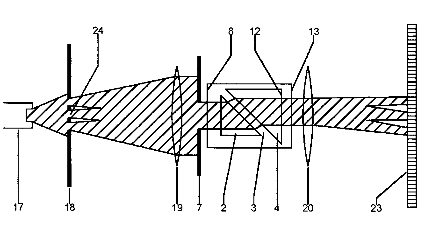
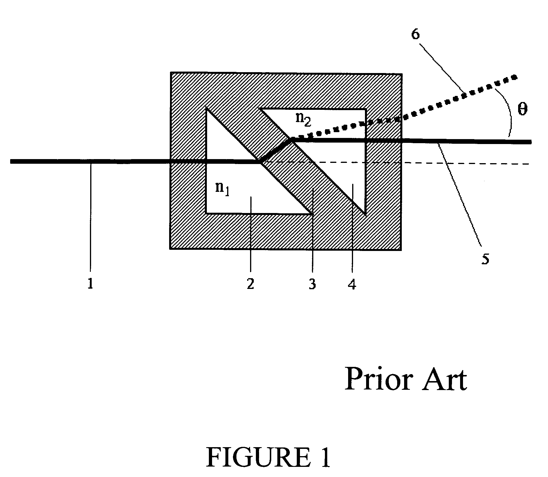
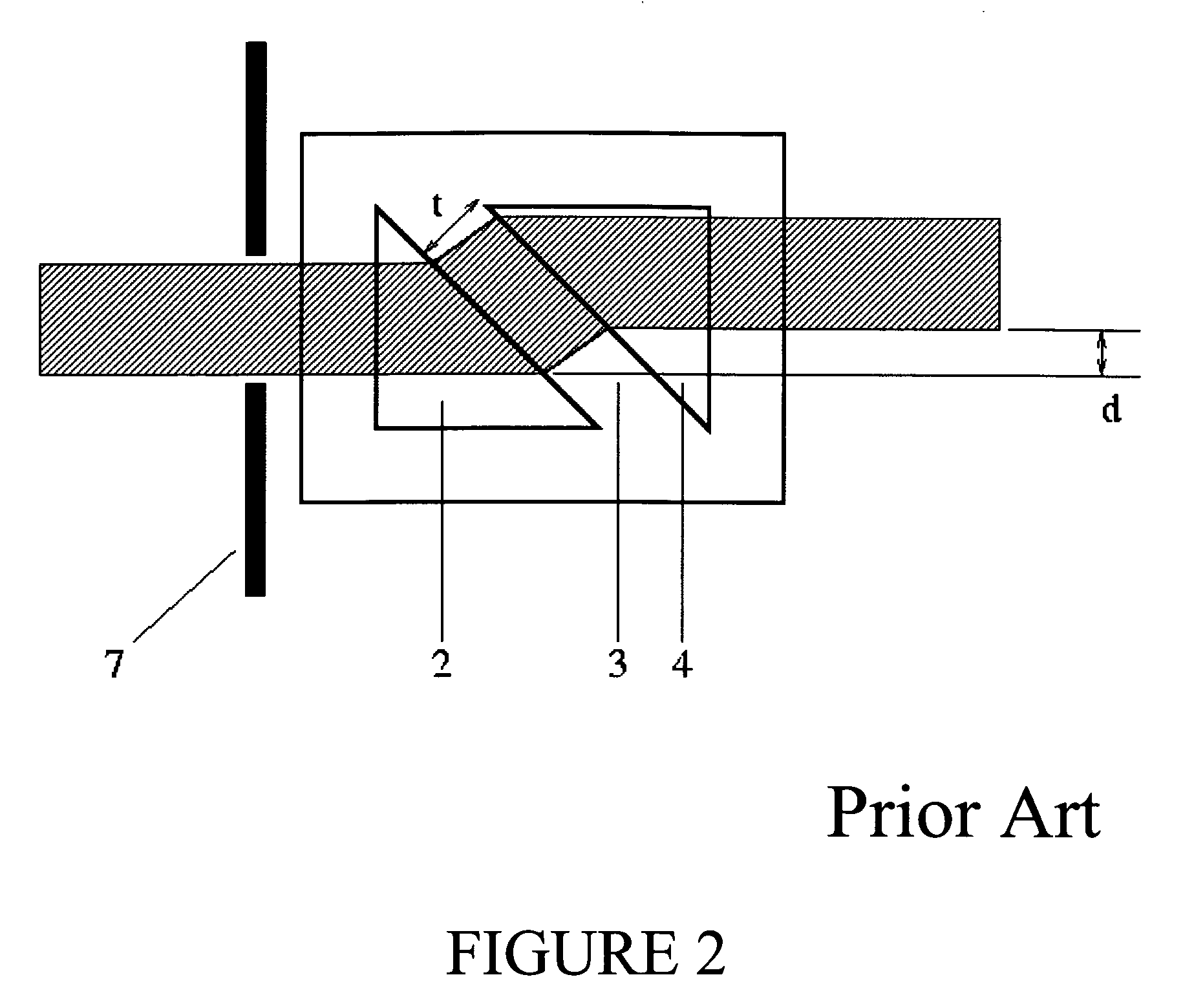
[0041]The objective of all dRI detectors is to measure the refractive index difference between the reference and sample fluids. For a walk-off type dRI detector, this is accomplished by measuring the angular deflection of the light beam emerging from the cell after traversing it. The translation of the emerging beam relative to the incident beam contributes to limit the sensitivity of the conventional cell structure by reducing the region within the sample chamber which may be illuminated and still have that light reach and traverse the reference chamber. This translation has a major dependence upon the refractive index difference between the sample fluid refractive index and that of the transparent material of which the cell is fabricated, and a minor dependence on the refractive index difference between the sample and reference fluids. For most practical applications, especially those related to the field of liquid chromatography, the refractive index difference between the two fl...


PUM

PropertyMeasurementUnit
refractive indexaaaaaaaaaa
transparentaaaaaaaaaa
diameteraaaaaaaaaa

Abstract

An improved differential refractometer incorporating a photodetector array is disclosed. Using a multi-element photo array provides the basis for measurement of differential refractive index values with a heretofore unattainable combination of sensitivity of measurement and concurrent range of measurement. Within the large dynamic range attainable, the detector structure provides equal sensitivity irrespective of deflection within the range. The transmitted light beam is tailored to provide a spatial variation of the light intensity at the array improving thereby the precision of measurement of its displacement. This in turn results in improved precision in the reported differential refractive index and in the calculation of the differential refractive index increment dn / dc. Integrating the detector array into the flow cell structure of the parent case results in a detector of exceptional sensitivity and range for sample quantities far smaller than required by conventional differential refractometers.

Description

CONTINUATION-IN-PART[0001]This application is a continuation-in-part of Ser. No. 10 / 768,600 filed 29 Jan. 2004 now U.S. Pat. No. 6,975,392, M. Larkin, “Enhanced Sensitivity Differential Refractometer Measurement Cell”RELATED AND OTHER CO-PENDING APPLICATIONS[0002]Expressly incorporated herein are the following related patents and concurrent applications. These are of importance as the present invention insures that they may be used and implemented more effectively:[0003]Ser. No. 10 / 723,548 filed 25 Nov. 2003, M. Larkin, “Refractometer Cell for both Absolute and Differential Refractive Index Measurement of Fluids.”[0004]U.S. Pat. No. 4,616,927—“Sample Cell for Light Scattering Measurements,” (Oct. 14, 1986)[0005]U.S. Pat. No. 5,530,540—“Light scattering measurement cell for very small volumes,” (25 Jun. 1996)[0006]U.S. Pat. No. 6,411,383—“Method for measuring the 2nd virial coefficient,” (25 Jun. 2002).[0007]U.S. Pat. No. 6,651,009—“Method for determining average solution properties ...

Claims


Application Information

Patent Timeline
Patent Type & Authority Patents(United States)
IPC IPC(8): G01N21/41G01N21/15
CPCG01N21/4133
Inventor LARKIN, MICHAEL I.TRAINOFF, STEVEN P.
Owner WYATT TECH
Why Eureka
Try Eureka