
Combined harmonic filter and phase converter or phase shifting device

a phase converter and harmonic filter technology, applied in the direction of reactive power adjustment/elimination/compensation, ac network to reduce harmonics/ripples, emergency protective arrangements for limiting excess voltage/current, etc., can solve the problem of reducing the electromagnetic compatibility of loads, consuming substantially higher current, and substantially higher dc bus voltage ripple level

Inactive Publication Date: 2006-04-11
1761911 ONTARIO
View PDF3 Cites 13 Cited by
  • Summary
  • Abstract
  • Description
  • Claims
  • Application Information

AI Technical Summary

Benefits of technology

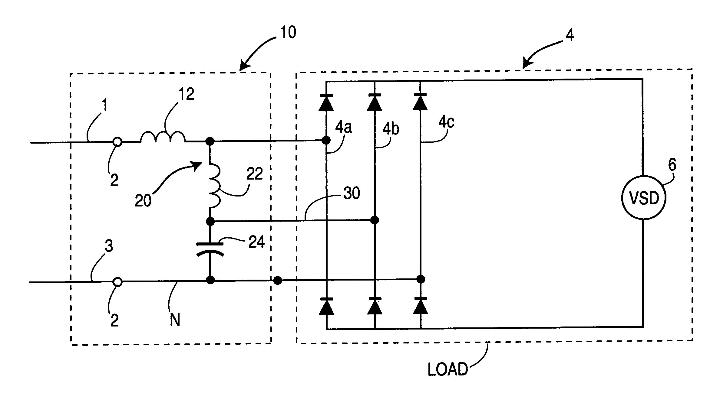
[0021]The present invention overcomes these disadvantages by providing a harmonic mitigating device that also functions either as a single-phase to three-phase converter for supplying single-phase non-linear loads or, using the same principles of the invention, as a phase shifting device for three-phase non-linear loads with multiple inputs to create a quasi multi-pulse system. In both cases the device is connected between the power supply and the load, and substantially reduces the levels of selected harmonic currents flowing into the power supply system.
[0025]The line and crosslink windings are preferably wound on a common core, which reduces the cost of the device. However, the line and crosslink windings may alternatively be wound on different cores which may or may not be magnetically coupled.
[0031]The present invention further provides a method of phase conversion and harmonic mitigation in a power distribution system supplying electrical power to a multi-phase load, comprising the steps of: a. supplying power from a first line comprising a first phase of the power distribution system to a first phase of the load, through at least one line winding, b. diverting power, through a crosslink circuit comprising at least one crosslink winding having a first end connected to a load end of the line winding and a second end connected through a capacitor, to a second line, and c. supplying power from the crosslink circuit to a second input of the load through a phase shifted output between the second end of the crosslink winding and the second phase of the load, to thereby phase shift the second phase of the load relative to the first phase of the load.

Problems solved by technology

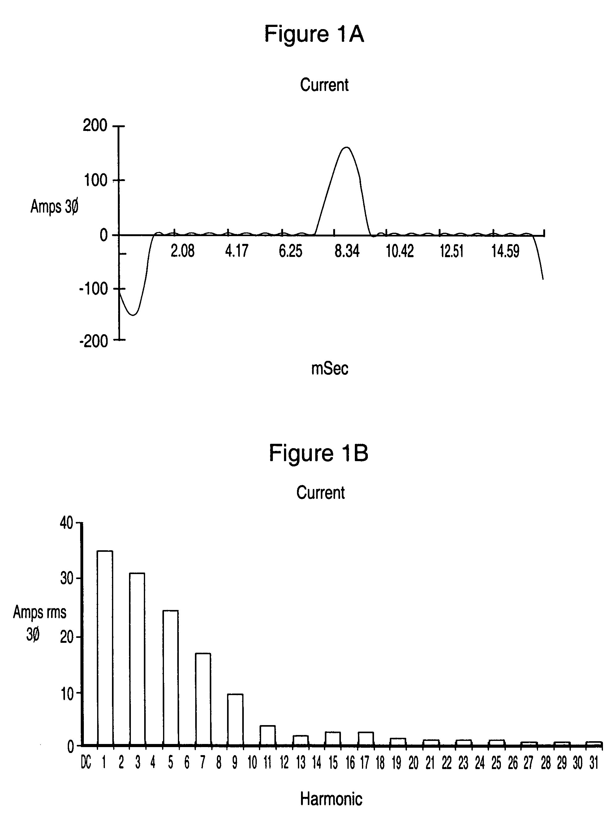
When non-linear and other harmonic generating loads are connected to a three-phase system, harmonic currents are fed back into the power supply and can cause many problems, such as reducing the electromagnetic compatibility of the loads and overheating of transformers.
However, in rural locations, and other remote locations such as oil fields, often the electrical distribution system provides only a single phase.
In addition to higher harmonic levels, when connected to a single-phase power supply such loads consume substantially higher current and have a substantially higher level of DC bus voltage ripple.
This results in increased losses in the system and requires that the harmonic generating drive be de-rated, i.e. larger than the optimum rated drive, so as to consume less current and reduce DC bus voltage ripple.
PFC's are relatively expensive devices and their applications are limited.
Also, PFC's cannot be retrofitted for use with existing power supplies, and are not practical for use with large ASD's.
Active filters have many disadvantages, including high cost, poor reliability and poor dynamic characteristics.
Active filters also are not practical for use with large ASD's.
These devices present many problems which are well known to those skilled in the art, including high cost, poor effectiveness in low voltage systems and the tendency to cause the system to operate with a leading power factor.
Further, because L-C filters are non-directional they are easily overloaded by untreated harmonic currents generated by other harmonic sources connected to the power distribution system (for example in a neighbouring facility), resulting in overloading and frequent failures of the filter's capacitor bank.
This technique is simple, reliable and relatively low cost, however it results in a high voltage drop across the reactors.
To reduce the voltage drop one must reduce the choke reactance level, which commensurately reduces the effectiveness of the choke and substantially limits harmonic current mitigation.
However, such systems are typically limited in terms of the number of harmonic orders which can be mitigated, and the degree of harmonic mitigation depends upon the extent to which harmonics produced by the various harmonic sources and their phase shift angles are identical.
This system addresses a large number of harmonic mitigating problems, but also provides certain drawbacks as a result of high internal impedance of the harmonic mitigating device.
The prior art for two-phase to three-phase converters falls into two basic types:
1. Mechanical converters such as rotating or dynamo-electric machines (motor-generators) in which a single-phase motor drives a three-phase generator. This conversion method is expensive and provides low reliability and high losses. Moreover, such devices introduce substantial impedance into the circuit supplying the non-linear load. The result is a high level of voltage distortion and reduced electromagnetic compatibility of the loads.
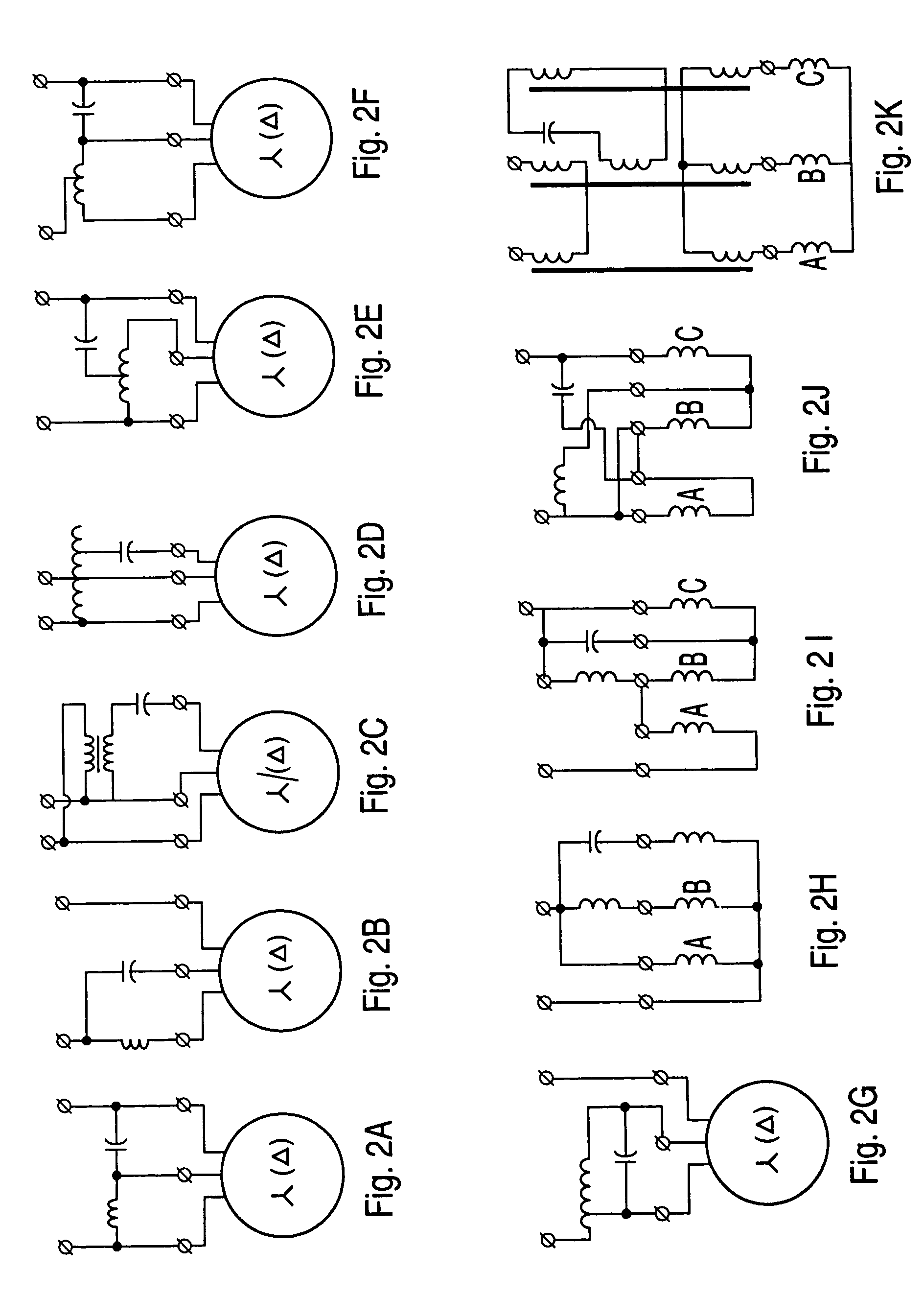
2. Various types of inductor-capacitor (L-C) networks. Examples of prior art configurations of two-element L-C networks for converting single-phase to three-phase are shown in FIGS. 7A to 7K. Examples of configurations of three-element prior art L-C networks for converting single-phase to three-phase are shown in FIGS. 7L to 7P. Examples of configurations of single-element prior art L-C networks for converting single-phase to three-phase are shown in FIGS. 7Q to 7T.
None of these prior art phase converters has any significant effect on harmonic currents generated by non-linear loads, and in fact in many cases the phase converter increases voltage distortion, thus making the situation worse.
High levels of harmonic currents create many problems in power supply and distribution systems, including increased total harmonic distortion level of the voltage, reduced electromagnetic compatibility of the loads, reduced liability of the equipment resulting in higher maintenance costs and increased down time of the system, increased power losses, reduced power factor and other problems that are well known to those skilled in the art.
The prior art does not provide a system which combines harmonic mitigation and phase conversion.
A reduction of other levels of harmonic currents using the same phase shifting principles requires an 18-pulse or 24-pulse rectification system, with associated additional cost and space requirements.
Furthermore, this solution is not available in a single-phase system.
This de-rating substantially increases the cost of the system, and requires the use of additional harmonic mitigating equipment that further increases the cost and space requirements of the power system.

Method used


Image

  • Combined harmonic filter and phase converter or phase shifting device
  • Combined harmonic filter and phase converter or phase shifting device
  • Combined harmonic filter and phase converter or phase shifting device

Examples


Embodiment Construction

[0049]A preferred embodiment of the invention for use in a three-phase power distribution system is illustrated in FIG. 6. Terminals 2a, 2b, 2c connect the device 10 to the lines 1a, 1b, 1c transmitting the three phases of the power supply. The power distribution system (not shown) may be any three-phase alternating current system, and the load 4 may comprise one or more harmonic generating loads, for example a variable speed drive (VSD) 6 with a bridge rectifier 8 for converting the alternating current to a direct current for driving the VSD 6. The rectifier bridges may be connected in parallel or in series. The DC output of each bridge may be provided with reactors to equalize the current distribution between the bridges, as is conventional.

[0050]Each line winding 12a, 12b, 12c comprises a first end connected to a first line, i.e. one phase of the power distribution system, and a second end connected to one phase 4a, 4b or 4c of the load 4. Each line winding 12a, 12b, 12c comprise...


PUM


Abstract

A harmonic mitigating device also functions as a phase converter for supplying single-phase non-linear loads, or as a phase shifting device for three-phase non-linear loads with multiple inputs to create a quasi multi-pulse system. A multiple-winding reactor or a plurality of single-winding reactors, and at least one capacitor, are connected in a crosslink circuit between the reactor windings, or between the reactor windings and another line. At least one reactive element comprising a line winding is connected to each phase or to the neutral and in series with a non-linear load, which provides a high reactance to harmonic currents, and at least one crosslink circuit comprising a second reactive element connected between the second end of the line winding and a capacitor which is connected to any other line in the system.

Description

FIELD OF THE INVENTION[0001]This invention relates to harmonic mitigating devices. In particular, this invention relates to a harmonic filter and phase converter or phase shifting device for single- and three-phase electrical power distribution systems.BACKGROUND OF THE INVENTION[0002]In urban areas in North America a typical electrical distribution system provides three phases. When non-linear and other harmonic generating loads are connected to a three-phase system, harmonic currents are fed back into the power supply and can cause many problems, such as reducing the electromagnetic compatibility of the loads and overheating of transformers.[0003]In a three-phase power distribution system, the phases can be phase shifted relative to one another, to suppress or completely cancel many of the more harmful harmonic currents. However, in rural locations, and other remote locations such as oil fields, often the electrical distribution system provides only a single phase. In these cases ...

Claims


Application Information

Patent Timeline
IPC IPC(8): H02H3/00H02J3/01H02J3/18H02J3/26
CPCH02J3/01Y02E40/40
Inventor LEVIN, MICHAEL I.HOEVENAARS, ANTHONY H.VOLKOV, IGOR V.
Owner 1761911 ONTARIO
Learn More