Multi-signal transmit array with low intermodulation

a multi-signal transmit array and low intermodulation technology, applied in the field of multi-signal transmit array with low intermodulation, can solve the problems of non-linear distortion, non-linear distortion of non-linear amplifiers, and non-linear amplifiers generating unwanted signals, and achieve the effect of reducing unwanted out-of-band radiation and improving transmission efficiency

Inactive Publication Date: 2006-04-11
ERICSSON INC
View PDF53 Cites 161 Cited by
  • Summary
  • Abstract
  • Description
  • Claims
  • Application Information

AI Technical Summary

Benefits of technology

[0014]A feature of the transmitter is the simultaneous transmission of multiple signals while employing single-signal amplifiers to reduce unwanted out-of-band radiation due to intermodulation distortion.
[0015]Another feature of the transmitter is improved efficiency of transmission using multiple, directive beams to transmit information to user terminals at different locations on the earth.

Problems solved by technology

However, a problem with this prior art configuration is that imperfect MCPA linearity causes nonlinear distortion or intermodulation between the signals generating unwanted signals.
These unwanted signals may lie outside the allocated frequency band, potentially interfering with other services.
Even when each signal alone, and thus their linear combinations formed by a beamformer, are band limited, the non-linearly amplified combinations will exhibit out-of-band spectral components due to the non-linear distortion.
While a single-signal phased array for transmitting a signal in a highly directive beam may of course be provided in multiple copies in order to transmit multiple signals, the total aperture area of the plurality of single-signal antenna arrays is inefficiently used since only a fraction of the antenna elements are used to radiate each signal.

Method used


Image

  • Multi-signal transmit array with low intermodulation
  • Multi-signal transmit array with low intermodulation
  • Multi-signal transmit array with low intermodulation

Examples


Embodiment Construction

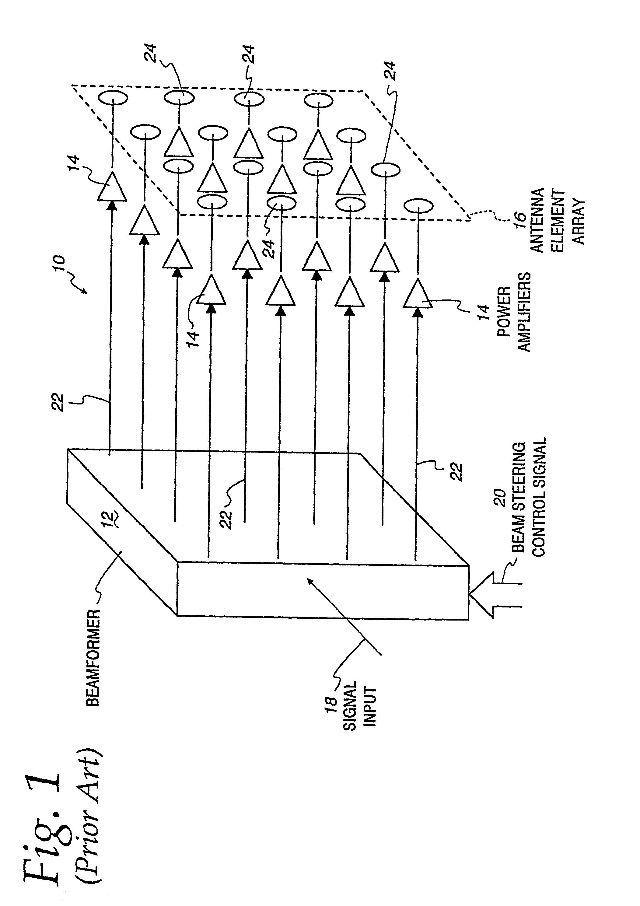
[0030]FIG. 1 illustrates a prior art transmitter, identified generally as 10, for transmitting a single signal. The transmitter 10 includes a beamformer 12, a plurality of power amplifiers 14 and an antenna element array 16. The beamformer 12 has a single input for a single signal 18 to be transmitted, and a beam steering control signal input 20 for determining directions of transmission. The beamformer 12 receives the input signal 18 and generates a number of output signals 22 for driving the power amplifiers 14, with each output signal 22 having a phase relative to the other output signals 22 determined by the beam steering control input signal 20.

[0031]Each power amplifier 14 is connected to a respective one of antenna elements 24 in the antenna element array 16. Each of the antenna elements 24 can alternatively be a sub-array of several elements 24 connected in a predetermined manner. By altering the relative phasing of the output drive signals 22, via the beamformer control sig...


PUM


Abstract

A transmitter is provided for simultaneously transmitting a plurality of signals in a plurality of directive beams to corresponding destination stations, each destination station located in a separate fan within a service area. The transmitter includes a plurality of beamformers, each beamformer receiving one of the signals to be transmitted to an associated fan, each of the beamformers having a plurality of outputs for each different signal to be transmitted. A plurality of Butler matrices each receive one of the plurality of outputs from the plurality of beamformers for each different signal to be transmitted, each Butler matrix having a plurality of outputs in phased relationship to one another, wherein each of the signals to be transmitted is simultaneously provided across the outputs of each Butler matrix in a phased relationship. An antenna is provided with an aperture within which a two-dimensional array of antenna elements are disposed, wherein equal fractions of adjacent antenna elements are connected to the outputs of each Butler matrix, and wherein each of the plurality of signals are simultaneously transmitted by the entire two-dimensional array of antenna elements. Each of the plurality of beamformers receives steering control signals for steering the direction of each beam within its respective fan.

Description

[0001]This is a division of Application No. 09 / 055,490, filed Apr. 6, 1998 now U.S. Pat. No. 6,377,588.TECHNICAL FIELD OF THE INVENTION[0002]The present invention is directed toward an active phased array transmitter for transmitting multiple signals and, more particularly, toward an active phased array transmitter for simultaneous transmission of multiple signals with a minimum of intermodulation distortion between signals.BACKGROUND OF THE INVENTION[0003]Transmitters having active phased array antennas, i.e., phased array transmitters, are commonly used in the transmission of signals. Active phased array transmitters can be configured to transmit signals in highly directive beams by using multiple antenna elements each connected to an elementary transmitter power amplifier. The signals are fed through each power amplifier and are relatively phased to achieve constructive addition of radiation in the desired direction. When only a single signal is to be transmitted in a single beam...

Claims


Application Information

Patent Timeline
Patent Type & Authority Patents(United States)
IPC IPC(8): H04L12/28H01Q3/40H01Q21/06H01Q25/00
CPCH01Q3/40H01Q25/00H01Q21/061H04B7/18515H04B7/2041
Inventor DENT, PAUL W.
Owner ERICSSON INC
Why Eureka
Try Eureka