Multiplexer, demultiplexer and multiplex communication system
- Summary
- Abstract
- Description
- Claims
- Application Information
AI Technical Summary
Benefits of technology
Problems solved by technology
Method used
Image


Examples
Embodiment Construction
[0032]Now, preferred embodiments of the present invention will be described hereinbelow with reference to the accompanying drawings.
[0033]In this embodiment, the present invention is applied to an optical multiplex communication system wherein two optical pulse train signals are interleaved on a time axis, i.e. time-division multiplexed, to produce a multiplexed optical pulse train signal in a multiplexer and the received multiplexed optical pulse train signal is demultiplexed to extract one of the two optical pulse train signals in a demultiplexer.
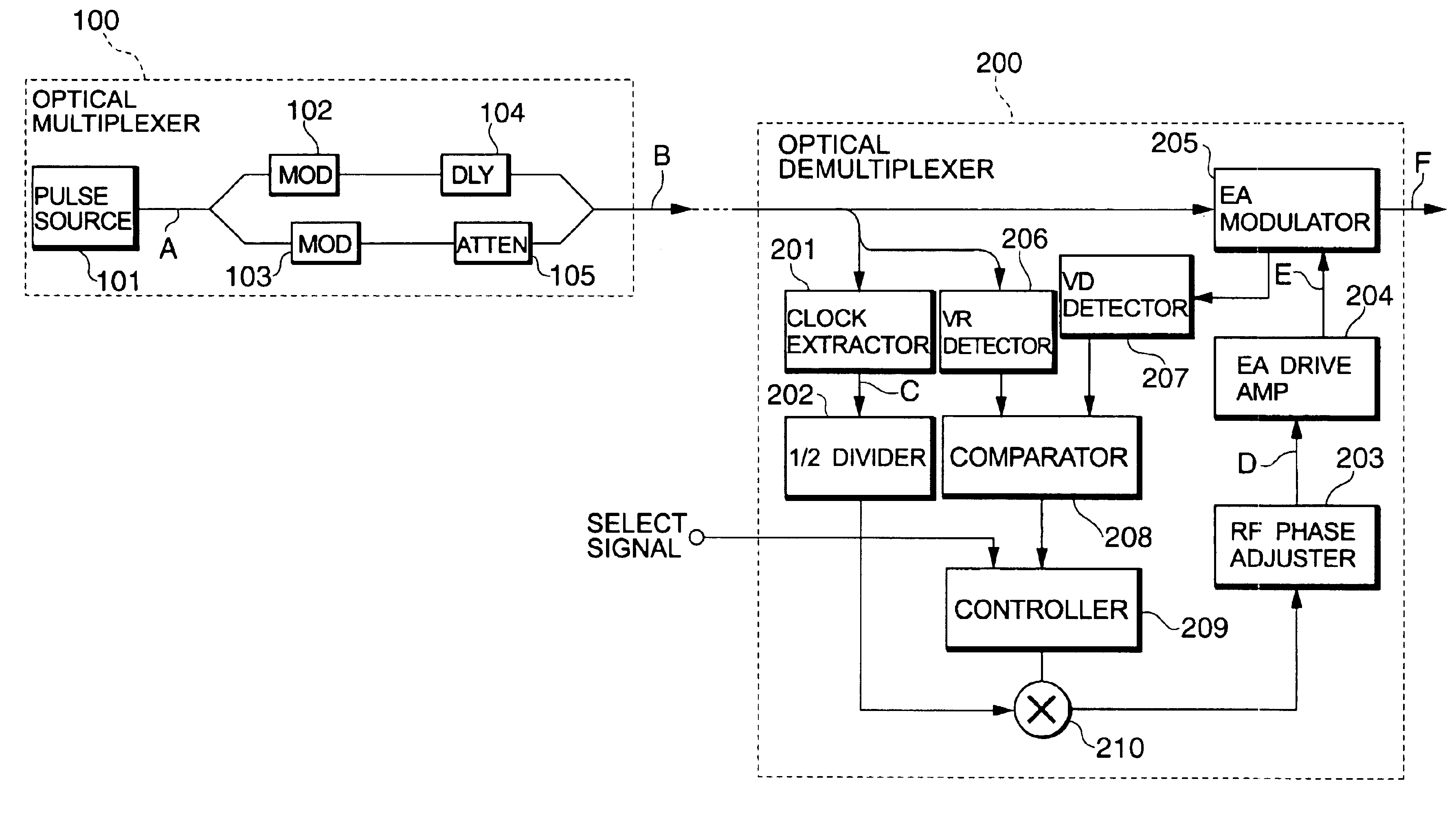
[0034]FIG. 1 shows a structure of an optical multiplex communication system having an optical multiplexer 100 and an optical demultiplexer 200 according to the first preferred embodiment of the present invention. In FIG. 1, the optical multiplexer 100 comprises an optical pulse source 101, a modulator 102, a modulator 103, a delay circuit 104 and an optical attenuator 105. On the other hand, the optical demultiplexer 200 comprises a clock...
PUM
 Abstract
Description
Claims
Application Information