Livestock food processing mixing machine

a technology of mixing machine and livestock, which is applied in the field of livestock food processing mixing machine, can solve the problems of mixing machine, no one said mixing machine offers what the market demands, and material bubble, and achieves the effects of reducing material waste, reducing material waste, and reducing material was

Inactive Publication Date: 2006-04-18
TORMEX IND DE C V
View PDF10 Cites 6 Cited by
  • Summary
  • Abstract
  • Description
  • Claims
  • Application Information

AI Technical Summary

Benefits of technology

[0011]The main object of the present invention is to offer a livestock food mixing machine having the capacity to mix different ingredients or materials independently from their size, consistence or humidity, on a quicker and efficient manner, and at the same time having the capacity to efficiently crush and / or grind ingredients having long fibers, independently if they are dry or humid, and being aware not to alter mixing times, good mixture quality, low power requirements, low maintenance rates and low cost, since the above will result in cost savings for livestock food products farmers and stockbreeders, reaching a higher competitiveness.
[0013]On the other hand, this same upper worm has a discs system mounted on a spiral arrangement, which in turn has exchangeable knives strategically placed on the peripheral portion thereof. Said knives are passed through a counterplate, which is also equipped with exchangeable knives placed at the bottom of a material-collector chute. This design allows that both, humid and dry fibers be efficiently ground and / or crushed and besides other several common ingredients to be used, a unique and highly qualified mixing is achieved.

Problems solved by technology

There are several mixing devices, which mixing technique consists basically of a bottom chamber for moving the material from the back portion to the front portion of said machine, through a worm, striking said material with a reverse loop at the discharge height; thus resulting in a material bubble.
But none of said mixing machines offer what the market demands now a days, which is to incorporate hay, grasses and fodder with long humid fibers, which could be quickly and efficiently ground within same mixer.
Generally, common failures in the mixing machines lies on the use of these long humid fibers that due to the lack of user control are incorporated into these mixtures, tangling up within the worms until damaging the equipment.

Method used


Image

  • Livestock food processing mixing machine
  • Livestock food processing mixing machine
  • Livestock food processing mixing machine

Examples


Embodiment Construction

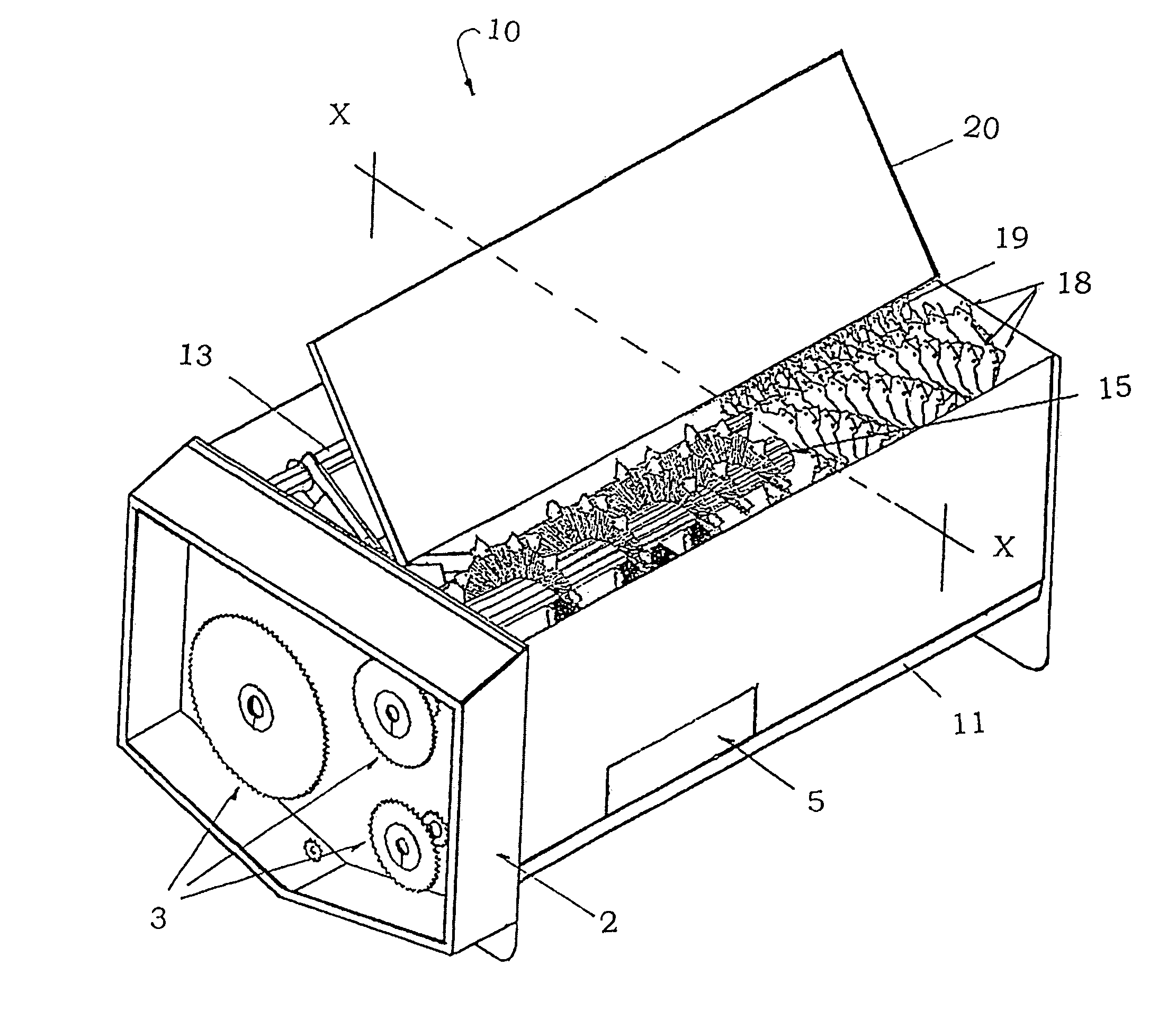
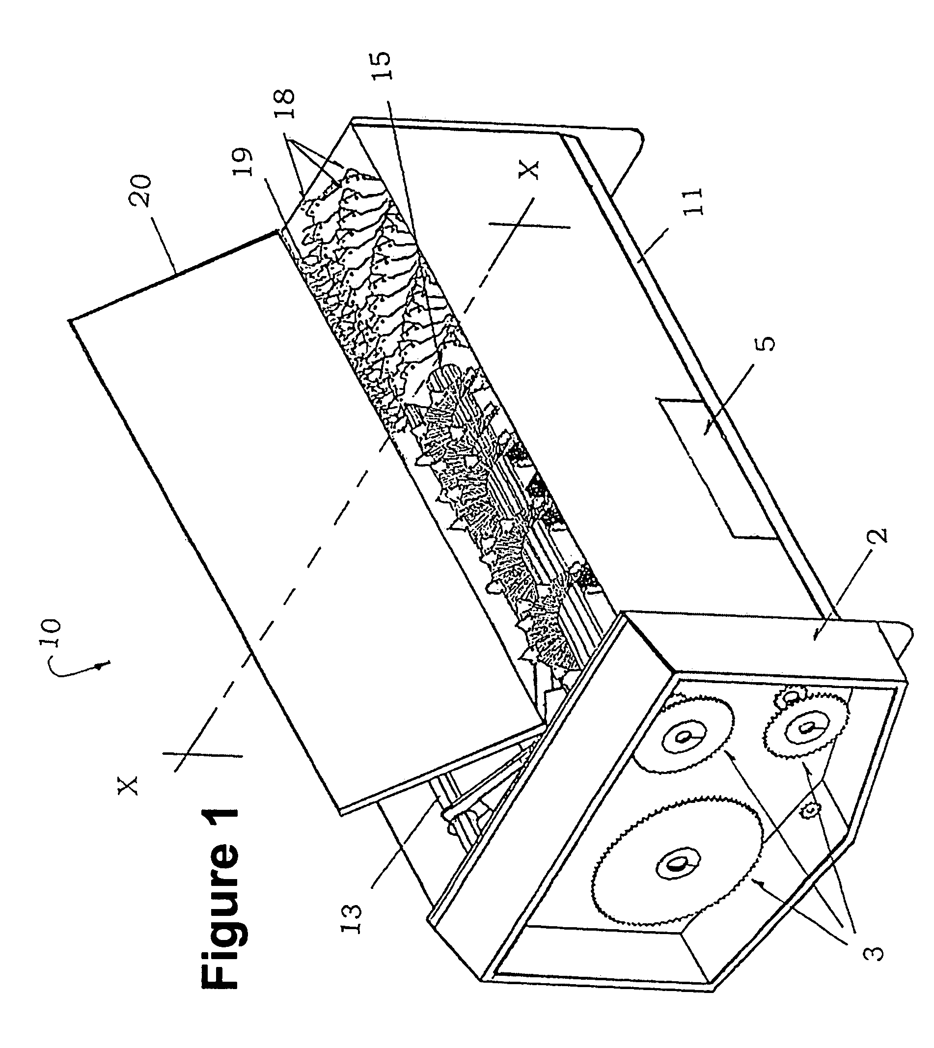
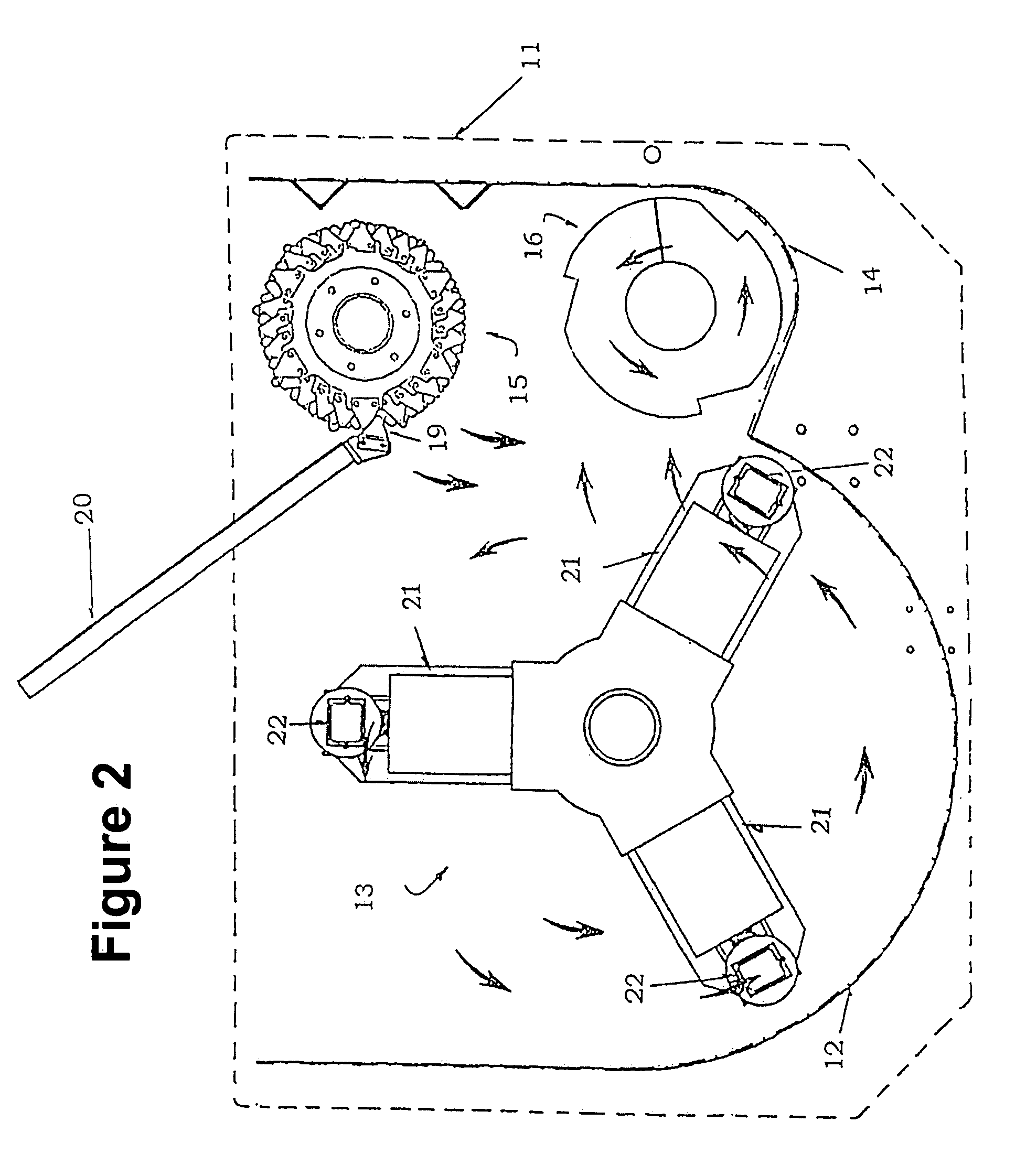
[0021]Firstly, it is important to show that there are several mixing system components similar to those of the present invention, that have been mentioned before; this is, this mixing machine has a hopper 11 that can be mounted upon a chassis (not illustrated) and that in turn can be towed through conventional means, such as a tractor, a vehicle, etc., said hopper 11 shows on its upper end, a housing 2 where on its inner part has a rotary gear system, where said system is mainly based on sprockets and chains, see FIG. 1, where only sprockets 3 by themselves are illustrated, in order to visualize the arrangement of said gear system, since for those skilled in the art it is easy to understand said system. This gear system is accessed through a removable cover lid 4 (see FIG. 5); where the gear system transmits the rotary movement for both, rotor 13 as well the pair of worms 15,16 located inside the hopper 11, to complete the homogeneously mixing of different materials used for feeding...


PUM


Abstract

A mixing machine consists of a hopper having a main chamber within its housing with a rotary member, a secondary chamber having a bottom worm conveying the material from one end of the mixing machine to the other end thereof, until collapsing with a loop found on its front portion and generating a material bubble; an upper worm to remove the material bubble and carrying it up to the middle part of the machine. At the middle part of the machine, the material is forced by a loop system having an upper worm to move towards the rotor area, such that the material is actually moving towards the back portion of the machine, completing a mixing cycle. The upper worm has from the middle of its axis, a plurality of discs on which peripheral edge of each disc is mounted a series of exchangeable knives placed on a loop arrangement, which are passed through a counterplate, and which shows a series of exchangeable knives placed at the bottom part of the material collector chut, so when the upper worm discs plurality is rotating, it allows both, humid and dry fibers be efficiently crushed and / or ground and besides added to the other several common ingredients a unique and highly qualified mixing is achieved.

Description

FIELD OF THE INVENTION[0001]The present invention relates to a livestock food mixing machine. More specifically, the present invention is related to a system that ensures a better mixing and grinding of food for livestock in a shorter time.BACKGROUND OF THE INVENTION[0002]Fodder, pasture, and grains, among others, are common livestock food components, that can be used alone or mixed and which constitute the reason of the existence of several types of mixing machines.[0003]There are several mixing devices, which mixing technique consists basically of a bottom chamber for moving the material from the back portion to the front portion of said machine, through a worm, striking said material with a reverse loop at the discharge height; thus resulting in a material bubble. Said bubble is removed by a superior worm that carries the material to the back machine portion and in such way that closes the mixing cycle.[0004]Mixing techniques that are closer to our invention are previously disclo...

Claims


Application Information

Patent Timeline
Patent Type & Authority Patents(United States)
IPC IPC(8): B02B5/02A23N17/00B01F7/00B02B3/06B02C1/08A01F29/01A01F29/06A01K5/00B01F7/02B01F7/04B01F13/00B01F13/10B01F15/00B02C18/14B02C18/22B02C19/00
CPCA01K5/002B01F13/105B01F7/047B01F7/00291B01F7/00416B01F7/00491Y10S366/603B01F15/00863B01F2013/108B01F27/1125B01F27/1143B01F27/1155B01F27/706B01F33/833B01F33/83611B01F35/52
Inventor MAIZ, JAVIER VILLARREAL
Owner TORMEX IND DE C V
Why Eureka
Try Eureka