Method for cutting a block of material and forming a thin film

a technology of material block and thin film, which is applied in the direction of coatings, microstructural devices, microstructured technology, etc., can solve the problems of inability to apply mechanical efforts on the source substrate and/or the target support, and inability to meet the requirements of thermal treatment at too high temperature,

Inactive Publication Date: 2006-04-18
COMMISSARIAT A LENERGIE ATOMIQUE ET AUX ENERGIES ALTERNATIVES
View PDF14 Cites 28 Cited by
  • Summary
  • Abstract
  • Description
  • Claims
  • Application Information

AI Technical Summary

Benefits of technology

[0020]The invention is based on the fact that it is possible to reduce significantly the overall energy for providing the block (either of thermal origin and / or mechanical origin) for implementing a cutting out process, by forming a separation initiator before the actual separation.
[0029]As an illustration of implantation techniques, one can refer to the documents quoted above. Nonetheless, thanks to the formation of a separation initiator, according to the invention, the doses of the species implanted to form the embrittled zone can be reduced. The reduced doses make it possible to lower the disturbance of the state of the surface of the thin films, or parts cut out, and thus to control the rugosity.

Problems solved by technology

The compatibility of materials can also constitute an obstacle to the direct formation of a thin film on a support substrate on which it is finally used.
The implementation of techniques for cutting out and transferring a thin film, as described in the documents quoted above, can be linked to a certain number of difficulties.
For example, the use of certain materials with a high thermal expansion coefficient is not compatible with a thermal treatment at too high a temperature.
The application of mechanical efforts on the source substrate and / or the target support is however not always possible, especially when the materials being used are brittle, or when the cleavage zone has not been sufficiently embrittled by ionic implantation.
Finally, the techniques of separation and transfer of the thin film, described above, involve a certain number of restrictions and compromises.

Method used


Image

  • Method for cutting a block of material and forming a thin film
  • Method for cutting a block of material and forming a thin film
  • Method for cutting a block of material and forming a thin film

Examples


Embodiment Construction

[0012]The aim of the invention is to propose a cutting out method making it possible, in particular, to form and transfer thin films, without the limitations mentioned above.

[0013]A further aim of the invention is to propose a cutting out method able to be implemented with a reduced energy budget and in particular a reduced thermal budget.

[0014]Another aim of the invention is to propose an economical process in which an eventual implantation of impurities, intended to form an embrittled zone, can be carried out with a reduced dose.

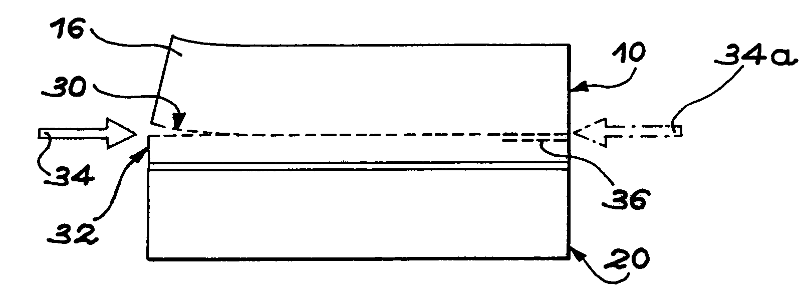
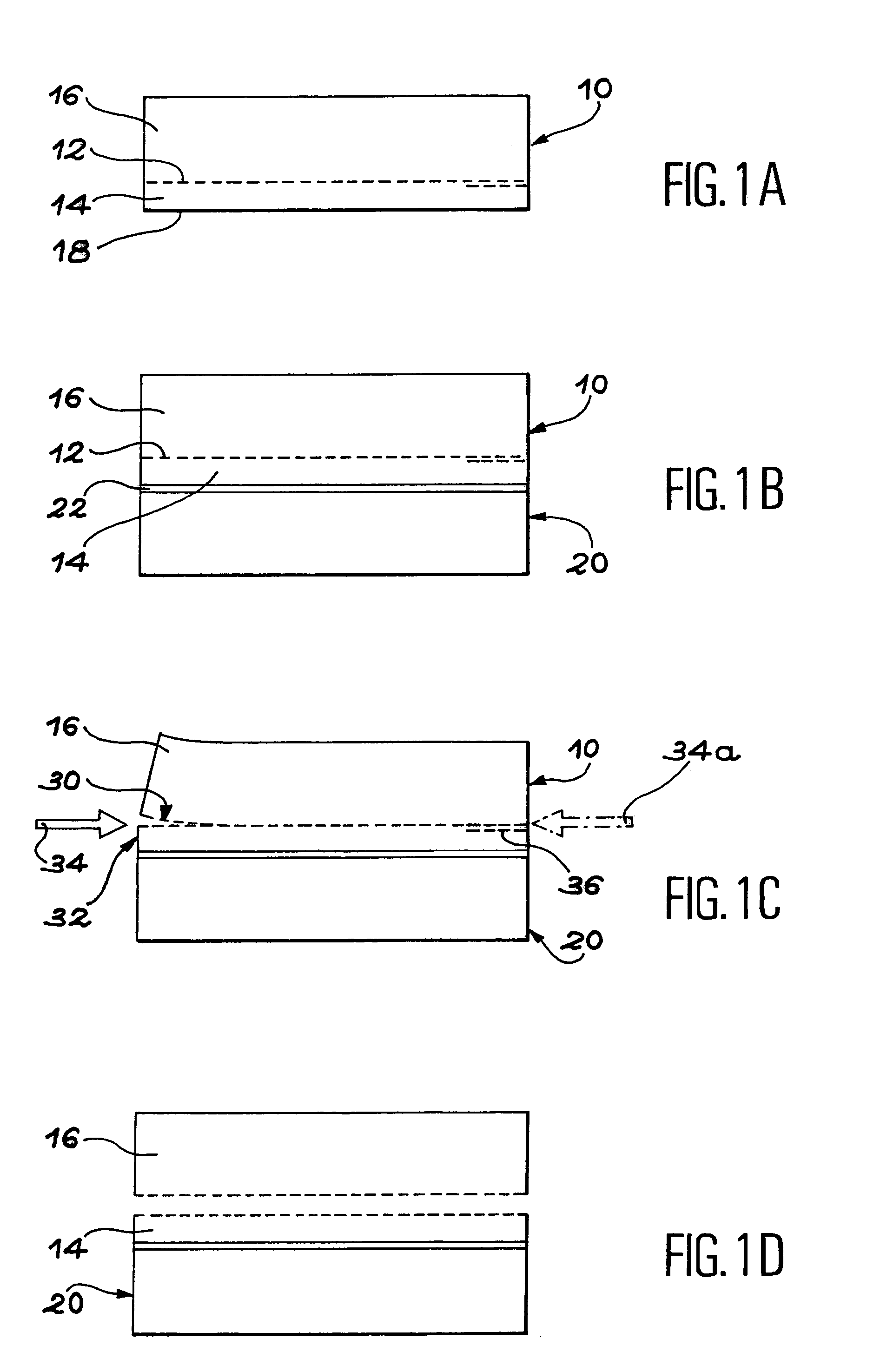
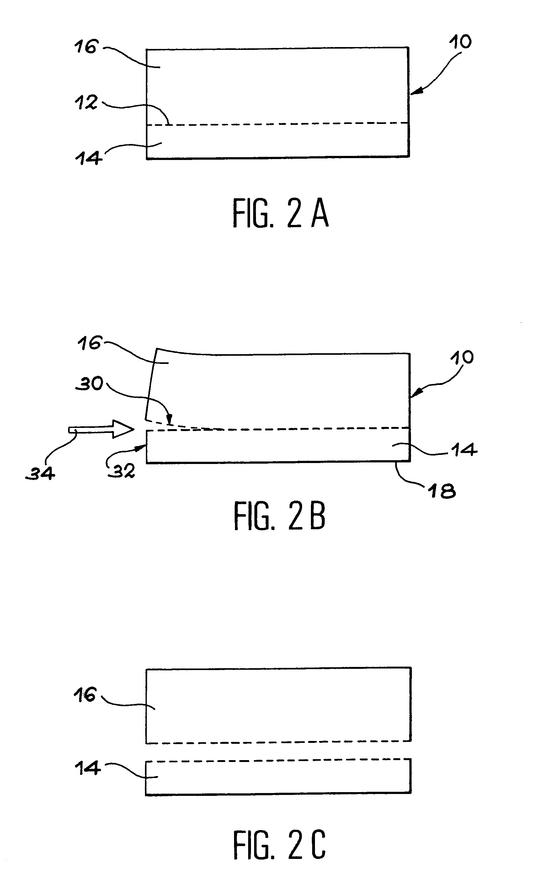
[0015]In order to attain these aims, the invention has more precisely the aim of a method for cutting out a block of material, comprising the following stages:

[0016](a) the formation in the block of a buried zone, embrittled by at least one stage of ion introduction, the buried zone defining at least one superficial part of the block,

[0017](b) the formation at the level of the embrittled zone of at least one separation initiator by the use of a first means...


PUM

PropertyMeasurementUnit
lengthaaaaaaaaaa
mechanical forcesaaaaaaaaaa
molecular contact adhesionaaaaaaaaaa

Abstract

A process for cutting out a block of material includes a step of introducing ions in the block thereby forming an embrittled zone and defining at least one superficial part of the block. The method also includes a step of forming at least one separation initiator at the level of the embrittled zone, wherein the step of forming the separation initiator includes implanting ions of an ionic nature different from that introduced during the preceding step. The method further includes a step of separating at the level of the embrittled zone the superficial part of the block from a remaining part of the block from the separation initiator, wherein the separation step includes at least one of a thermal treatment and the application of mechanical forces acting between the superficial part and the embrittled zone.

Description

TECHNICAL FIELD[0001]In a general way, the present invention relates to a process for cutting out a block of material. This process can be implemented, in particular, for the formation of thin films.[0002]Thin films, self-supporting or integral with a support substrate, are widely used in the fields of micro-electronics, opto-electronics and micro-mechanics. Thus the invention is applicable to these domains, in particular for producing components or integrated circuits.STATE OF PRIOR ART[0003]As mentioned above, the use of thin films is increasingly widespread for components whose operation or manufacturing method requires special physical and electrical properties.[0004]Thin films have a thickness which is usually comprised between a few nanometers and a few micrometers. They also make it possible, for example, to use materials whose usage under the form of a thick substrate would be ruled out for reasons of cost or compatibility with other materials used.[0005]The compatibility of...

Claims


Application Information

Patent Timeline
Patent Type & Authority Patents(United States)
IPC IPC(8): B44C1/17B44C1/00H01L21/265B81C1/00H01L21/02H01L21/20H01L21/301H01L21/762H01L27/12
CPCB81C1/0038H01L21/2007H01L21/76254B81C2201/0191B81C2201/0192Y10T156/1911Y10T156/1158Y10T156/1967Y10T156/1153Y10T156/1184H01L27/12
Inventor ASPAR, BERNARDLAGACHE, CHRYSTELLE
Owner COMMISSARIAT A LENERGIE ATOMIQUE ET AUX ENERGIES ALTERNATIVES
Why Eureka
Try Eureka