Aquaculture system

a technology for aquaculture and systems, applied in the field of aquaculture systems, can solve the problems of ponds becoming polluted, destroying stock, and almost impossible cleaning of ponds

Inactive Publication Date: 2006-04-18
CUMMINSCORP LTD
View PDF23 Cites 40 Cited by
  • Summary
  • Abstract
  • Description
  • Claims
  • Application Information

AI Technical Summary

Benefits of technology

[0024]Air conditioning means may be provided to control the temperature and humidity within the enclosed space of the building module and thus the temperature of air supplied to the foam fractionators and biological filter chamber. A controllable light source such as one or more lamps may be provided above the main chamber to create artificial day and night conditions within the building module.

Problems solved by technology

The ponds however eventually become polluted because faeces, uneaten food and algae work their way to the bottom of the ponds.
This makes the ponds almost impossible to clean.
In addition large quantities of valuable water are required to keep these systems functional.
Other disadvantages are also associated with outdoor aquaculture systems.
For example pests can eat stock, adverse weather conditions such as floods can cause stock loss by washing the stock away and very hot weather can cause growth of algal blooms which can kill the stock.
Muddy waters or disturbed water can also cause the stock to have an unpalatable taste.
In particular, there is a continuing circulation of the water around the system with the addition of approximately 10 percent of its water volume each week unlike in outdoor ponds where water is pumped in and then overflows back into streams and rivers causing added pollution.
The temperature control equipment is relatively expensive in capital cost and also running costs can be high.
Further, the buildings or sheds would have to be fully insulated to be viable and this would mean an impractical cost in relation to returns.
A further disadvantage of the known systems is that the buildings or sheds housing the aquiculture system resemble a maze of pipes and plumbing as water is pumped between the system components such as tanks, filters, biological filters, foam fractionators, ultraviolet water treatment units and other water treatment components.
One of the major problems with these system is that with a large number of pipes interconnecting the components, vibration in the pipes or simply the suspension of pipes can creates stresses causing pipe joints to fail and / or pipe fracture.
If such a failure occurs, water from the tanks is quickly lost resulting in the loss of tonnes of fish stock.
Further wherein there is a large volume of exposed piping, water temperature losses occur in cold climates and water temperature increases occur in hot climates resulting in massive increases in the electricity costs for cooling or heating the water.
This has in many cases made the indoor systems commercially unviable.
Another disadvantage which arises is that fish often attempt to jump out of the tanks so additional piping has to be placed over the top of the tanks and then covered with netting to prevent fish losses.
With regards to the individual components, if ultraviolet water treatment units are installed, they are installed into the main water flow pump line which reduces flow thus increasing the electricity consumption.
In the foam skimmers or foam fractionators which are used in the conventional systems, insufficient bubbles or foam is created or forced out of the top of the units.
If insufficient bubbles or foam is created, the fractionators simply do not function.
To make them function correctly, high pressure high energy pumps fitted with air venturis are employed but these do not always overcome the problem of inefficient operation.
If the water is stopped for any length of time, it can be very detrimental to the fish stock as in times of heavy stock loading, the fish can only stay alive for around six minutes before fatalities begin to occur.
Another major drawback is that if a bearing or another major mechanical failure happens, removal the drum filter and all of the fittings is extremely time consuming and in many cases can lead to total stock losses.
Cleaning of the current drum filters in any event is difficult as easy access cannot be had to the interior of the drum.

Method used


Image

  • Aquaculture system
  • Aquaculture system
  • Aquaculture system

Examples


Embodiment Construction

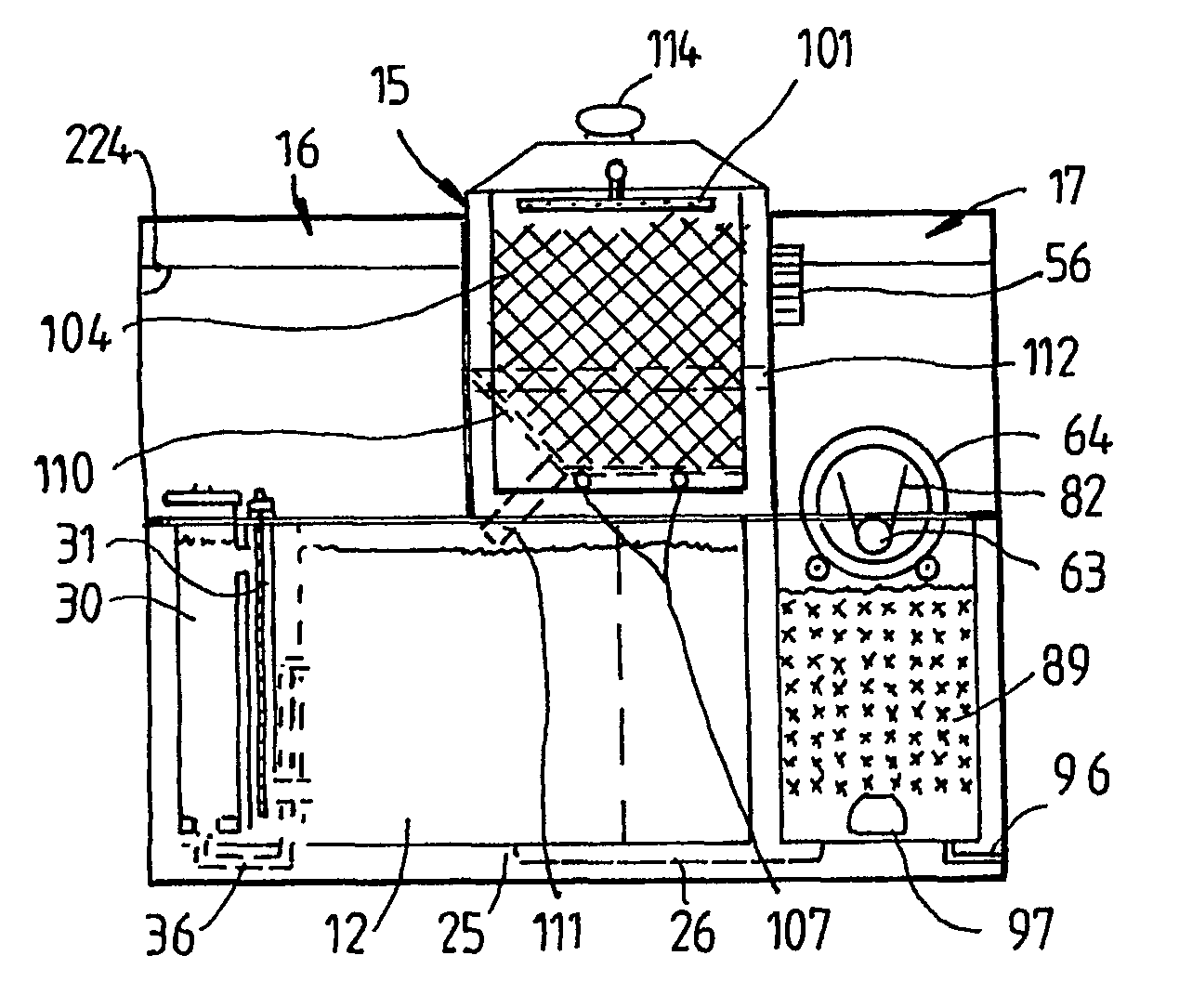
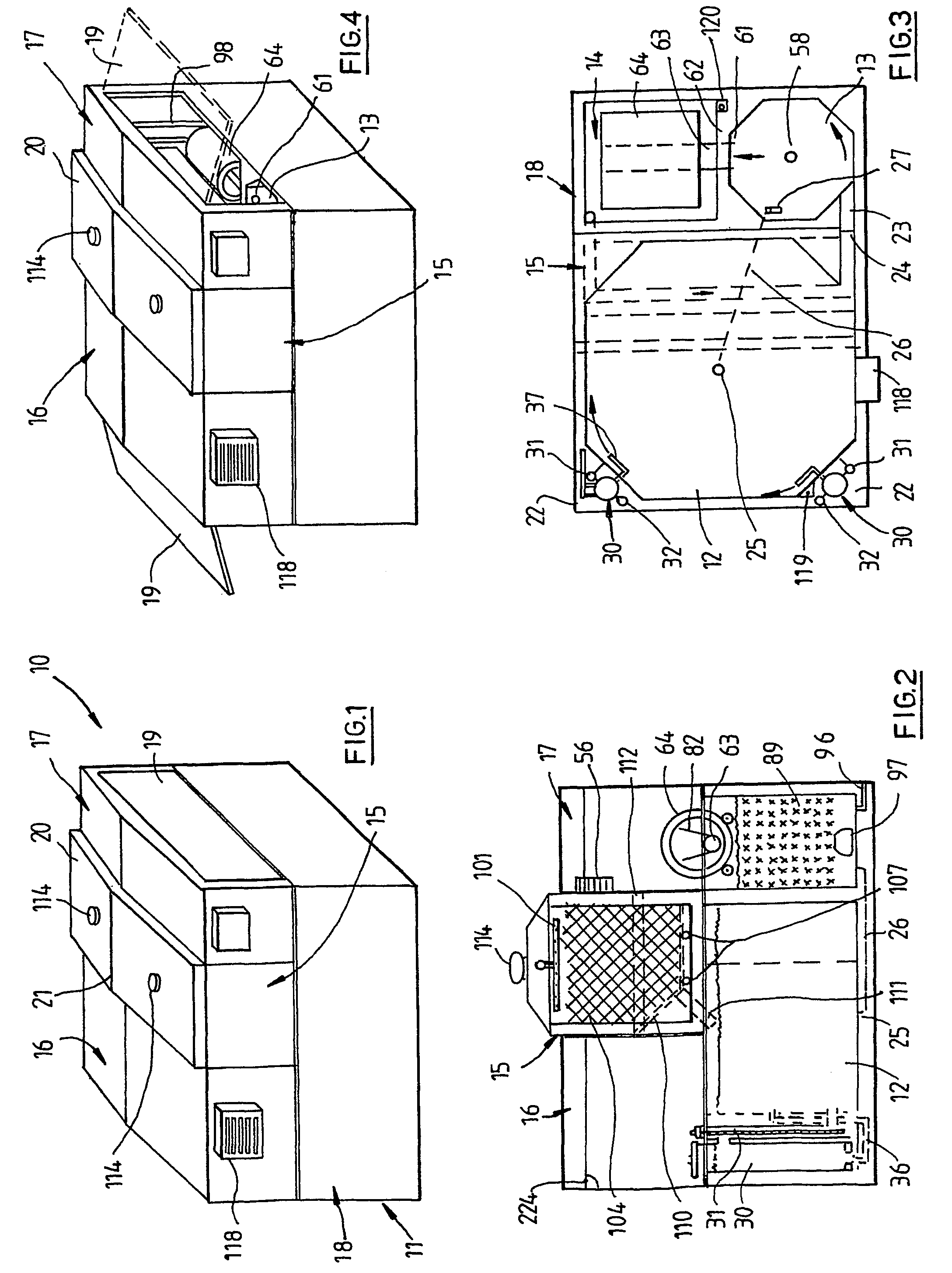
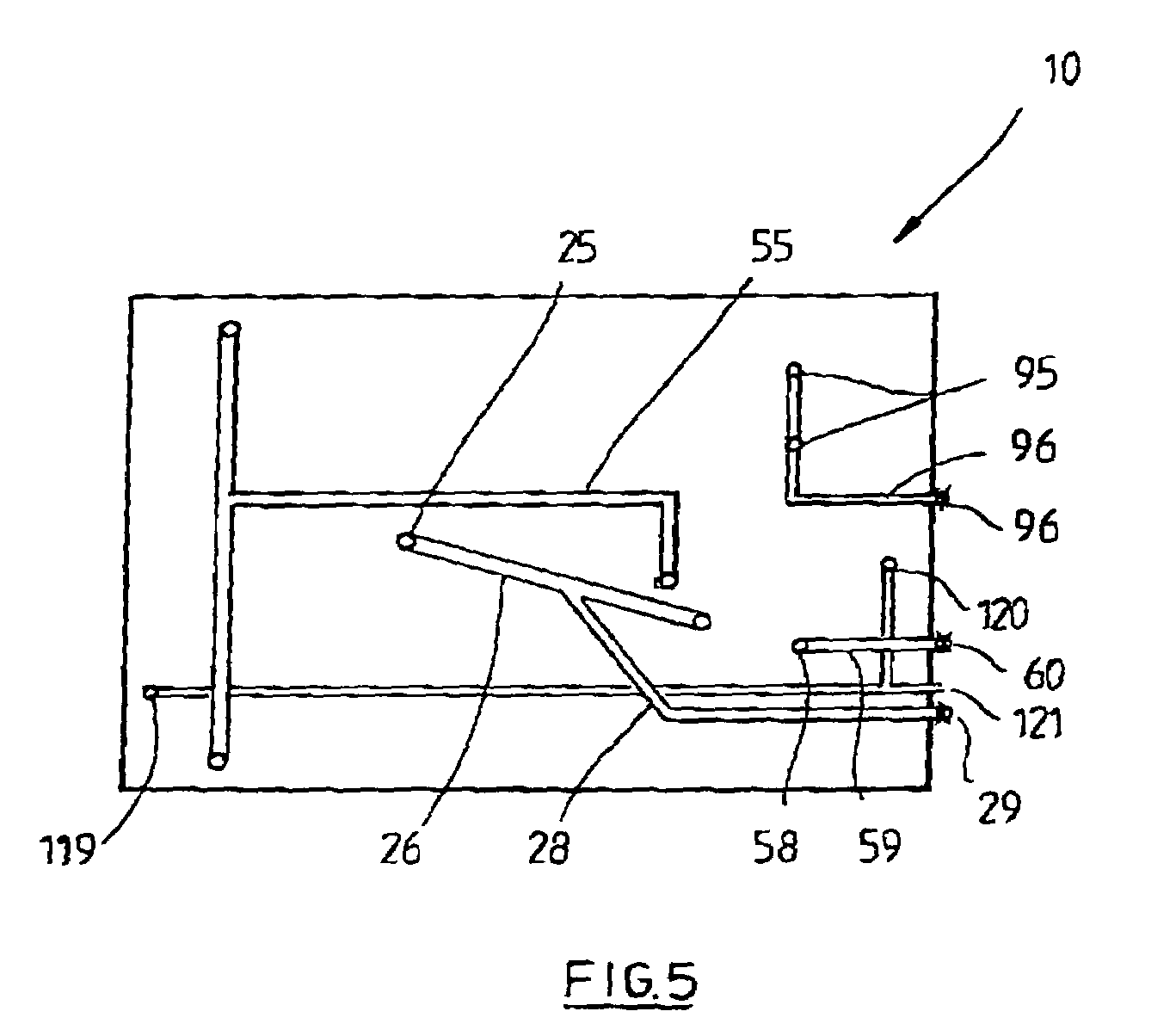
[0061]Referring to the drawings and firstly to FIGS. 1 to 4, there is illustrated an aquaculture system 10 in accordance with an embodiment of the invention in the form of a modular building 11 comprising and defining a main water chamber 12 for holding fish or marine invertebrates, a swirl chamber 13 which serves as a primary filter and a biological filter / drum or screen filter chamber 14 of a secondary filter. The chambers 12, 13 and 14 have their bases at substantially the same level; however the water level in each chamber is controlled such that the level in chamber 14 is less than the level in chamber 13 and the level in chamber 13 is less than the level in chamber 12. This then allows flow of water from the main chamber 12 to the swirl chamber 13 and then to the chamber 14 under the influence of gravity without pumping. The building module 11 also is defined by a biological filter tank 15 which is elevated and located above the main chamber 12. Opposite end integral hip roof ...


PUM

PropertyMeasurementUnit
temperatureaaaaaaaaaa
mouldableaaaaaaaaaa
rotationaaaaaaaaaa

Abstract

A self-contained aquaculture system comprising a modular building defining a first main chamber for containing fish or marine invertebrates, a second swirl chamber comprising a primary filter communicating with the main chamber for removing solids from the main chamber, a drum filter for receiving and filtering water from the swirl chamber, a third biological filter chamber beneath the drum filter for receiving water therefrom and a biological filter tank. Water is pumped from the chamber. The building defines an enclosed space over the chambers, the temperature of which is controlled by an air conditioning unit. A foam fractionator, ultraviolet unit and ozone generator are used for treating the water in the main chamber.

Description

TECHNICAL FIELD[0001]This invention relates to aquaculture systems for growing fish, prawns or other marine invertebrates. The present invention also relates to water treatment components used in aquaculture systems.BACKGROUND ART[0002]Aquaculture has commonly been conducted by growing fish, prawns and other marine invertebrates in outdoor ponds. The ponds however eventually become polluted because faeces, uneaten food and algae work their way to the bottom of the ponds. This makes the ponds almost impossible to clean. In addition large quantities of valuable water are required to keep these systems functional. Other disadvantages are also associated with outdoor aquaculture systems. For example pests can eat stock, adverse weather conditions such as floods can cause stock loss by washing the stock away and very hot weather can cause growth of algal blooms which can kill the stock. In addition in very hot or very cold weather, the stock will stop growing. Muddy waters or disturbed w...

Claims


Application Information

Patent Timeline
Patent Type & Authority Patents(United States)
IPC IPC(8): A01K63/04A01K61/00C02F1/32C02F1/78C02F3/06A01K63/00B01D24/46B01D33/06B01D33/15B01D33/27B01D33/44B01D33/58B01D35/027C02F1/24
CPCA01K63/00A01K63/04A01K63/042B01D33/11A01K63/045B01D33/48Y10S210/905Y02W10/37A01K61/10A01K61/59
Inventor CUMMINS, IAN GEOFFREY
Owner CUMMINSCORP LTD
Why Eureka
Try Eureka