Motor controller

a motor controller and controller technology, applied in the direction of electric controllers, ignition automatic control, instruments, etc., can solve the problems of time, manpower, and difficulty for beginners to adjust, and achieve the effect of short tim

Inactive Publication Date: 2006-04-18
MITSUBISHI ELECTRIC CORP
View PDF15 Cites 9 Cited by
  • Summary
  • Abstract
  • Description
  • Claims
  • Application Information

AI Technical Summary

Benefits of technology

[0015]The third aspect of the present invention causes the easy adjustment according to controlling specifications and characteristics of controlled objects and the appropriate adjustment in a short time corresponding to applications and characteristics of machines.

Problems solved by technology

It takes a time to individually adjust those; in addition, it is difficult for beginners to adjust those because they need knowledge to properly make the adjustment.
There have been problems in that not only it needs manpower and takes a time to make good adjustments in setting out individually a loop gain of a feedback loop, a pole frequency, a zero-point frequency, and the like, but also it is difficult without specialized knowledge.
In addition, controlling specifications are not standardized in such a point as to which is more prioritized, converging speed or response smoothness, depending on the applications in which the motor controlled is employed.
As a result, there have been problems in that conventional motor controller can not reach a properly adjust state by only adjustment by means of one input parameter, causing, in some cases, adjustment each being greatly deviated from the proper adjustments.

Method used


Image

  • Motor controller
  • Motor controller
  • Motor controller

Examples


embodiment 1

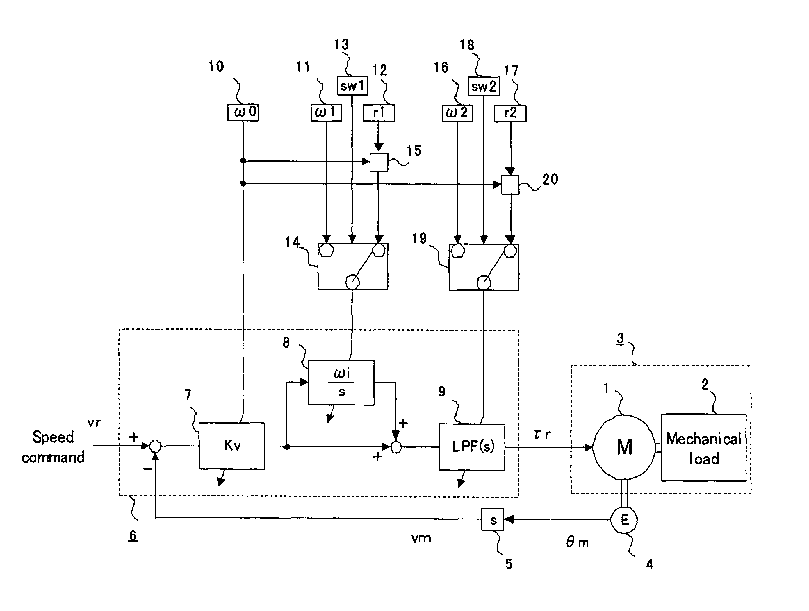
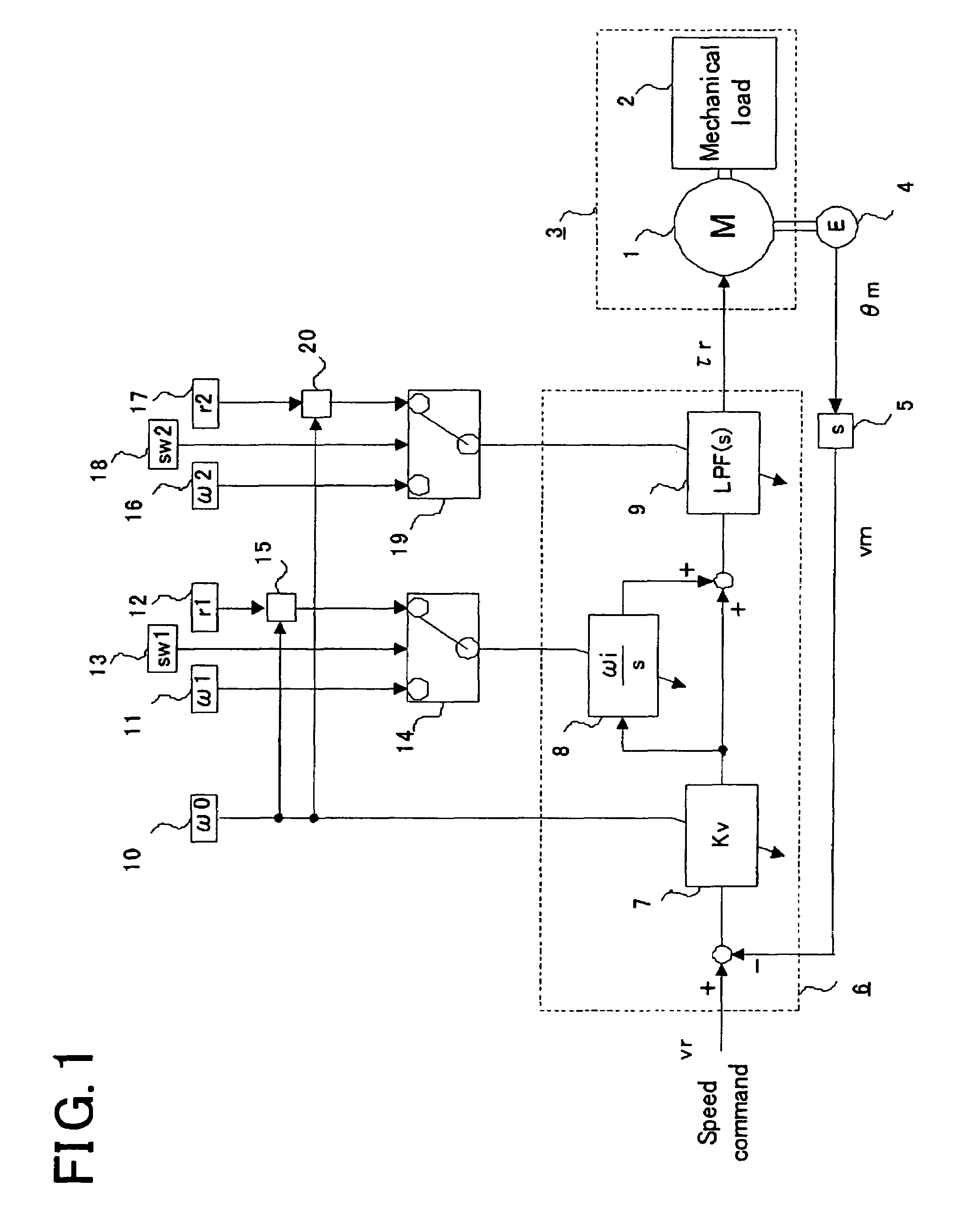
[0021]FIG. 1 is a block diagram illustrating a motor controller for Embodiment 1 of the present invention. A motor 1 generates a torque responding to torque commands τr, to drive a controlled object 3 composed of the motor 1 and a mechanical load 2 coupled with the motor 1. Moreover, a motor speed vm that is the rotational speed of the motor 1 is detected by detecting a motor angle θm that is the rotational angle of the motor 1 by an encoder 4, and then differentiating, by a speed computation unit 5, the motor angle θm.

[0022]Next, a speed command vr and the motor speed vm are inputted to a feedback computation unit 6, and the feedback computation unit 6 computes torque commands τr by the computation described below.

[0023]In the feedback computation unit 6, the difference signal between the speed command vr and the motor speed vm is inputted to a speed proportional amplifier 7, and the speed proportional amplifier 7 outputs the signal to multiply the input by a speed gain Kv. Next, t...

embodiment 2

[0046]FIG. 3 is a block diagram illustrating a motor controller relevant to Embodiment 2 of the present invention. The same numerals as those of FIG. 1 show the same units and their explanations are therefore omitted. This Embodiment is configured by adding to Embodiment 1 a mechanical characteristic estimation unit 51 and an input and an output thereof, and explanations will be made for these units.

[0047]The mechanical characteristic estimation unit 51 estimates a mechanical resonance frequency of the controlled object 3 based on the detected motor speed vm, for example, by such a method as measuring vibration frequency when motor speed vm oscillates. Moreover, it is judged which is better for the second switching signal sw2 to select the setting of an absolute value or the setting of a ratio, based on the estimated mechanical resonance frequency, and the estimation unit 51 sets out the result to the second switching signal input unit 18. As a judgment method, as explained in Embod...

embodiment 3

[0051]FIG. 4 is a block diagram illustrating a motor controller relevant to Embodiment 3 of the present invention. The present Embodiment relates to a motor controller that performs positional control, although Embodiment 1 and 2 relate to speed control. The same numerals as those of FIG. 1 show the same units and their explanations are therefore omitted.

[0052]A positional command θr and the motor angle θm are inputted into a feedback computation unit 106, and it computes the torque commands τr by the operation described next.

[0053]In the feedback computation unit 106, the difference signal between the positional command θr and the motor angle θm is inputted to a positional proportional amplifier 131, and then the positional proportional amplifier 131 outputs the signal, as the speed command vr, in which the input has been multiplied by positional gain Kp. Next, the difference signal between the speed command vr and the motor speed vm which the motor angle θm has been differentiated...


PUM


Abstract

This invention relates to a motor controller for driving an object to be controlled by torque from a motor responding to a computed torque command, the object being provided with the motor and a mechanical load. The motor controller includes: a feedback computation unit into which is inputted a positional command signal or a speed command signal, and a motor rotational signal which is a detected value of the motor's rotational angle or speed, the feedback computation unit being for computing the torque command by a computation in which the transfer function for a feedback loop from the motor rotational signal to the torque command includes a pole or a zero point; a response parameter input unit for inputting a response parameter; and a ratio parameter input unit for inputting a ratio parameter. A loop gain which is the gain of the feedback loop is determined based on the response parameter. The pole or the zero point of the feedback loop is determined based on the response parameter and the ratio parameter in such a way that the ratio of a response frequency which is quotient of the loop gain divided by an inertia value of the controlled object to a frequency corresponding to the pole or the zero point of the feedback loop is the value determined by the ratio parameter.

Description

BACKGROUND OF THE INVENTION[0001]1. Field of the Invention[0002]The present invention relates to a motor controller for a driving unit used in processing machines, semiconductor manufacturing equipment, various conveyance equipment, or the like.[0003]2. Description of the Related Art[0004]A motor controller needs to generate torque commands through a computation by a feedback loop based on a motor speed or a motor angle, and to properly set out a zero-point frequency, a filter frequency, and a pole and a zero point of a transfer function of the feedback loop and the like related to the loop gain and a speed PI control. It takes a time to individually adjust those; in addition, it is difficult for beginners to adjust those because they need knowledge to properly make the adjustment.[0005]Prior art that improves these adjustment described above, for example, is to configure the controller in such a way that one input parameter is inputted from outside and then the loop gain, pole and ...

Claims


Application Information

Patent Timeline
Patent Type & Authority Patents(United States)
IPC IPC(8): H02P7/00
CPCH02P27/026H02P2205/05Y10S388/906
Inventor IKEDA, HIDETOSHI
Owner MITSUBISHI ELECTRIC CORP
Why Eureka
Try Eureka