Body rest for magnetic resonance imaging

a magnetic resonance imaging and body rest technology, applied in the field of magnetic resonance imaging systems, apparatus and procedures, can solve the problems of limiting the imaging information obtained, affecting the comfort level of patients, and general claustrophobic environment of patients, so as to reduce the risk of patient movement during imaging, reduce the probability of patient movement, and increase the number of patients imaged

Active Publication Date: 2006-04-18
FONAR
View PDF33 Cites 14 Cited by
  • Summary
  • Abstract
  • Description
  • Claims
  • Application Information

AI Technical Summary

Benefits of technology

[0033]It may prove further desirable to position the patient such that the first fixture is adjusted to provide a rest area for the patient's buttocks and such that a second fixture is adjusted to provide a rest area for the patient's knee.
[0034]The method may further desirably include positioning the patient such that a portion of the patient's weight is supported by the patient's feet. The method also may desirably further include performing kinetic studies of the patient's shoulder region.
[0035]In accordance with the present invention, the risk of pa...

Problems solved by technology

Also, magnetic resonance imaging can obtain images of soft tissues and other features within the body which are not readily visualized using other imaging techniques.
Moreover, equipment of this type provides a generally claustrophobic environment for the patient.
This affects the conditions under which imaging may be performed and also affects the comfort level of the patient.
The positi...

Method used


Image

  • Body rest for magnetic resonance imaging
  • Body rest for magnetic resonance imaging
  • Body rest for magnetic resonance imaging

Examples


Embodiment Construction

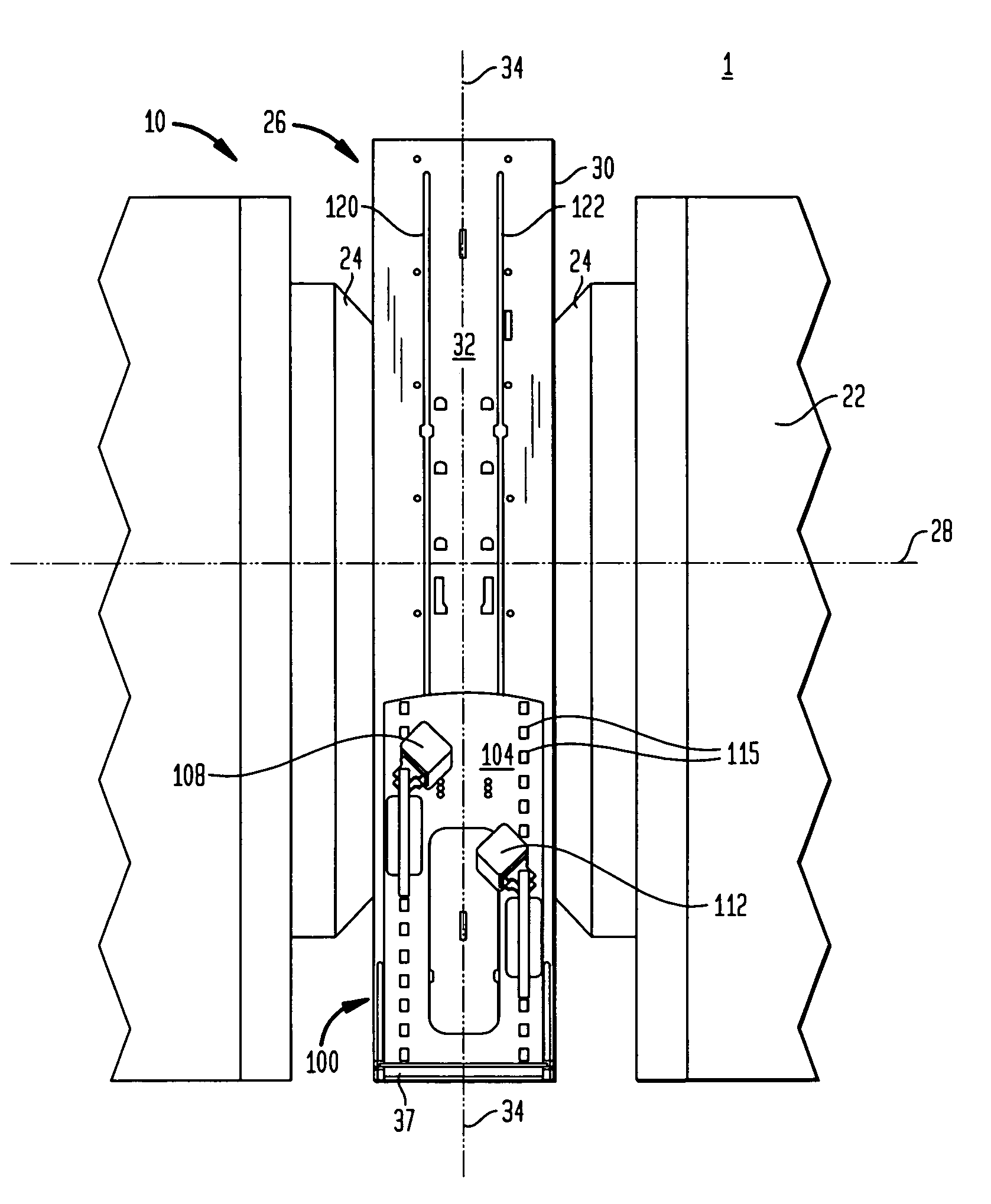
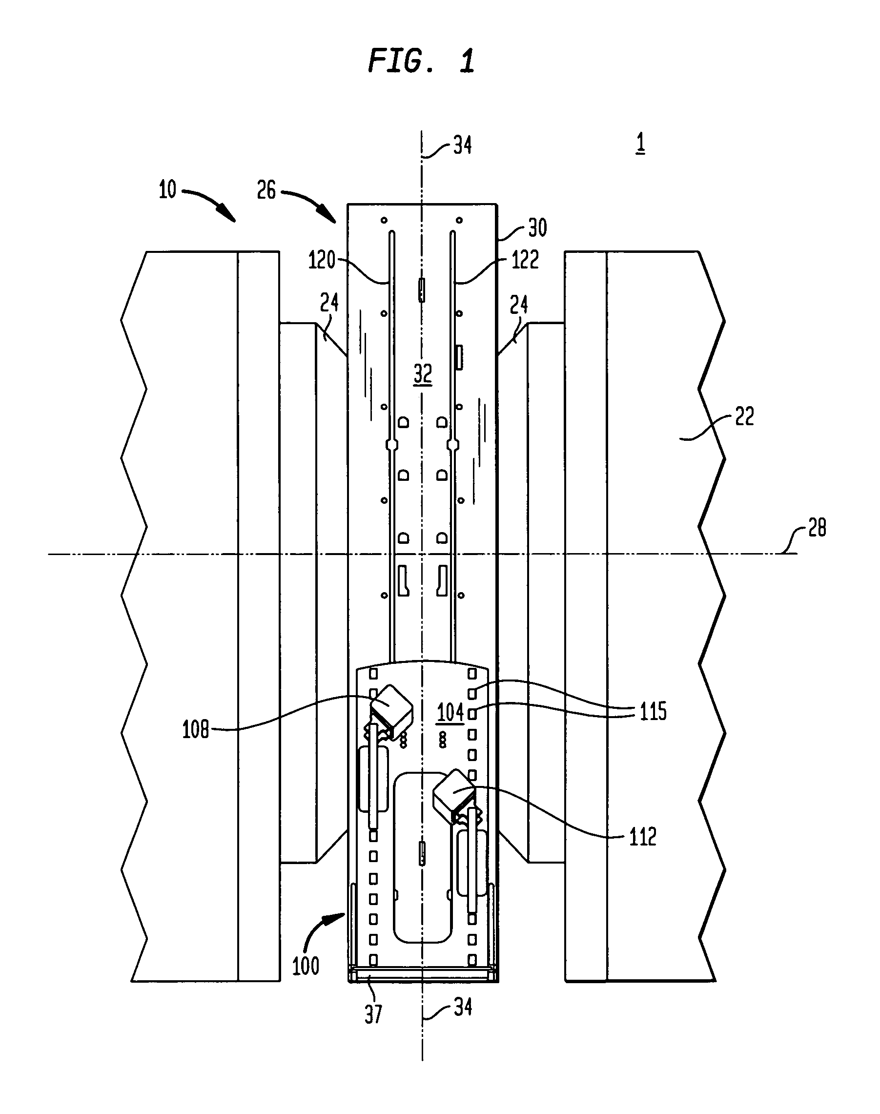
[0043]FIG. 1 depicts a front view of magnetic resonance imaging system 1 in accordance with an embodiment of the present invention. The system 1 includes a magnet resonance imaging apparatus 10, which is generally in accordance with the disclosure of the aforementioned commonly assigned U.S. patent and co-pending patent applications, the disclosures of which are incorporated by reference in their entirety herein. The resonance imaging apparatus 10 includes a magnet 22 comprising a pair of opposed elements 24 defining a patient-receiving space 26 between them. In the particular magnet illustrated, the opposed elements are pole faces. Other types of magnets may also be used and may comprise superconducting or resistive electromagnet coils or other structures. The magnet 22 is arranged to provide a magnetic field surrounding a magnet axis 28 within patient-receiving space 26. The magnet axis 28 as well as the magnetic field axis of the magnet extends in a substantially horizontal direc...


PUM


Abstract

System, apparatus and method for performing magnet resonance imaging. The apparatus comprises first and second members for distributing the weight of a patient to be imaged in a substantially upright position between the patient's knees and buttocks. The system comprises a horizontal field magnet magnetic resonance imaging apparatus in combination with the apparatus. In accordance with the method a patient is imaged in an ergonomic position with the patient's weight distributed between the patient's buttocks and knees.

Description

BACKGROUND OF THE INVENTION[0001]The present invention relates to magnetic resonance imaging systems, apparatus and procedures.[0002]In magnetic resonance imaging (“MRI”), an object to be imaged, as for example, a body of a human subject, is exposed to a strong, substantially constant static magnetic field. The static magnetic field causes the spin vectors of certain atomic nuclei within the body to randomly rotate or “precess” around an axis parallel to the direction of the static magnetic field. Radio frequency excitation energy is applied to the body, and this energy causes the precessing automic nuclei to rotate or “precess” in phase and in an excited state. As the precessing atomic nuclei relax, weak radio frequency signals are emitted; such radio frequency signals are referred to herein as magnetic resonance signals.[0003]Different tissues produce different signal characteristics. Furthermore, relaxation times are the dominant factor in determining signal strength. In addition...

Claims


Application Information

Patent Timeline
IPC IPC(8): G01V3/00
CPCA61B5/0555G01R33/3806A61B5/4528A61B5/055
Inventor DAMADIAN, JEVANWAHL, WILLIAM H.
Owner FONAR
Why Eureka
Try Eureka