
Photodynamic stimulation device and method

a technology of photodynamic stimulation and living tissue, which is applied in the field of electrotherapy devices, can solve the problems of decreasing the effectiveness of the device, the availability of infrared radiation within the range of 900 nm, and the inability of the known device to deliver a constant effect during use, so as to enhance the therapeutic capabilities of the device and enhance the vesicular respiration

Inactive Publication Date: 2006-04-25
LARSEN ERIK
View PDF9 Cites 96 Cited by
  • Summary
  • Abstract
  • Description
  • Claims
  • Application Information

AI Technical Summary

Benefits of technology

[0020]The present invention provides a device using red and infrared radiation of several wavelength ranges suited for the photodynamic stimulation of the cell energy in living cells, in particular human cells of both surface and underlying tissue. Furthermore, blue light is provided as well to enhance vesicular respiration, particularly stimulation of the ATP production in cells, thus enhancing the therapeutic capabilities of the device.
[0023]The invention provides multiple wavelength stimulation that is effective in conjunction with photodynamic therapy (PDT) chemicals. Such chemicals are applied or injected into or onto tissue to be treated, and subsequent photostimulation of them causes reactions in them that result in treating the tissue. Irradiation at multiple wavelengths enhances the effects of PDT chemicals while reducing discomfort to the patient.

Problems solved by technology

A disadvantage of the known device is that the semiconductor diodes during use tend to overheat, which causes a decrease in the effectiveness of the device.
The known device therefore does not deliver a constant effect during use.
Another disadvantage is that only infrared radiation within a range of 900 nm is available, while other wavelengths may be called for to achieve cell stimulation.
The housing also contains a fan to cool the lamp and filter but practical considerations concerning the size of the housing and the capacity of the fan typically result in insufficient cooling during operation, which causes the light output to vary.
This can result in improper hardening, and perhaps also shrinking, of the fillings.
And, the apparatus is bulky and thus unwieldy in use.
Recently however, there has been speculation that so-called silver fillings (actually mercury based) which have traditionally been used in the larger teeth may pose health risks, and many patients are requesting plastic fillings instead.
The difficulties of using the unwieldy halogen apparatus are thereby exacerbated.
For example, operating them at higher output results in temperature fluctuation, which in turn results in fluctuation of the light intensity which may result in improper hardening, and perhaps even shrinkage, of the fillings.
Singlet oxygen is toxic to protein and phosphorlipids in the tumor tissue, whereby the tumor is destroyed without destroying the surrounding tissue.
The light source typically used to irradiate PDT chemicals is commonly known as the surgical laser, a solid-state laser which is bulky, and which is expensive both to purchase and to operate.
Surgical lasers are designed primarily for cutting, i.e., they output very high energy in a very small spot, and are thus difficult to adapt to the requirement to irradiate a more generalized area for PDT.
Also, initial phases of such treatment often cause reactions, which in turn cause pain and discomfort.

Method used


Image

  • Photodynamic stimulation device and method
  • Photodynamic stimulation device and method
  • Photodynamic stimulation device and method

Examples


Embodiment Construction

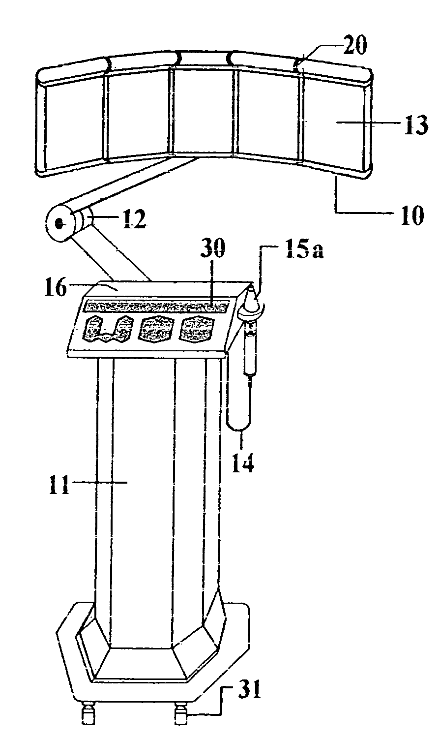
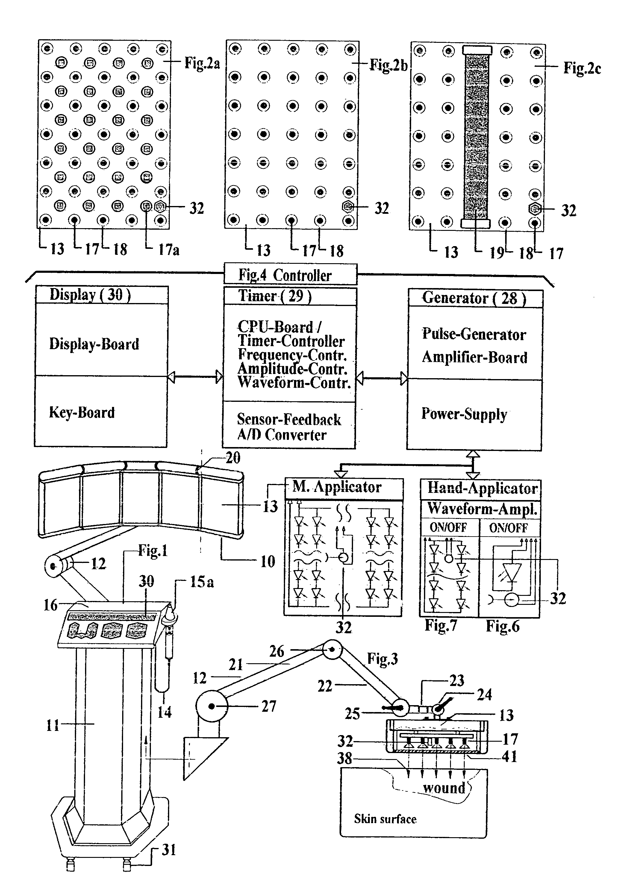
[0036]As shown in FIG. 1, the inventive device 10 for the energy stimulation of cells consists of a standpillar 11, with which machine applicators 13 (in the following just called applicators 13) are connected through a jointed arm 12. The standpillar 11 is also connected by an electric circuit 14 with hand applicator 15. The standpillar 11, freely movable on wheels, includes control mechanism 16 (described in FIG. 4). whereby the function of the control mechanism 16 can be adjusted and switched ON / OFF at a control board 30 (also called description equipment 30).

[0037]The FIGS. 2a, 2b and 2c show plain surfaced applicators 13. which can be used in the working model according to FIGS. 2a to 2c individually, side by side (in large numbers) or in combination with an applicator. According to FIG. 2a, the applicators 13 in the working model are mounted in a shifting order with semiconductor diodes 17 and 17a (in the following called diodes), whereby shifting the order of diodes 17 means,...


PUM


Abstract

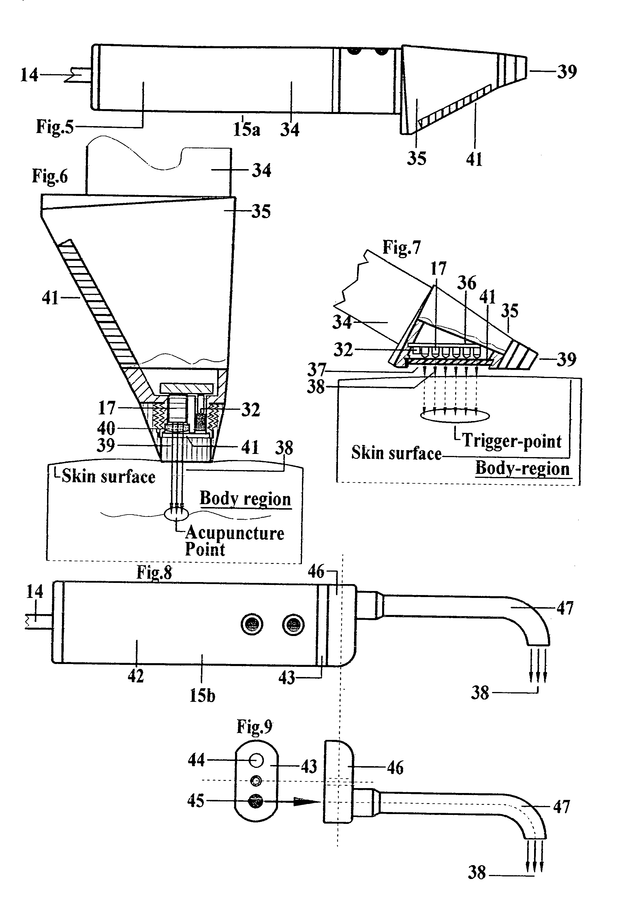
A treatment device which uses cold red and infrared radiation for the photodynamic stimulation of cells, especially cells of human tissue. The described device produces a constant energy radiation by the use of semiconductor and / or laser diodes, which furthermore radiate light in several separate wavelengths due to a special operation mode. With help of sensors the advanced controller system is able to test the patients for the needed radiation doses in order to avoid overstimulation. Furthermore the radiation openings in the applicators are advantageously covered with a polarization filter, whereby the absorption in the irradiated tissue is increased. The basic equipment consists of a standpillar, with which machine applicators are connected with a jointed arm. The machine applicators are adapted for the treatment of large area tissues, for example, the back of humans. The standpillar is freely movable on wheels and includes a control mechanism, whereby the various parameters for therapy can be adjusted and switched ON and OFF. The standpillar is also connected to a hand applicator designed for the treatment of small tissue areas, e.g., acupuncture points. Another version of the hand applicator is especially devised for dental treatment, whereby the head piece of the hand applicator can be connected with an expander containing an optical fiber. Photodynamic substances are introduced into tissue to be treated, which enhances the effects of light irradiation by the inventive device.

Description

CROSS-REFERENCE TO RELATED APPLICATIONS[0001]This application is a continuation-in-part of U.S. application Ser. No. 08 / 094,161 filed Dec. 20, 1993, now abandoned, which is a national stage of PCT Application No. PCT / CH92 / 00228 filed Nov. 20, 1992. The entire contents of both applications are incorporated by reference.BACKGROUND OF THE INVENTION[0002]1. Field of the Invention[0003]The present invention relates in general to electrotherapy devices and more particularly to devices and methods for photodynamic stimulation of living tissue, directly and also indirectly by stimulation of photosensitive substances introduced into or onto living tissue.[0004]2. Description of the Related Art[0005]Mitochondria within cells of protozoa and metazoa represent sources of energy delivering vesicular respiration. They are moreover capable of synthesizing proteins, because they dispose from the cell nucleus an independent or self-dependent genetic system of DNA and RNA.[0006]The mitochondria's mai...

Claims


Application Information

Patent Timeline
IPC IPC(8): A61F7/00A61B17/00A61C19/00A61HA61H39/00A61N5/06A61N5/073
CPCA61N5/0616A61N5/062A61N2005/073A61B2017/00057A61C19/004A61N2005/0663A61N2005/0642A61N2005/0652A61N2005/0659
Inventor LARSEN
Owner LARSEN ERIK
Learn More