Objective lens for optical disc

a technology of optical discs and objective lenses, applied in the field of objective lenses for optical disc drives, can solve the problems of optical system inability to correct the change of spherical aberration caused, the change of spherical aberration due to ambient temperature is overcorrected, and the disadvantage of the objective lens, so as to achieve sufficient tolerance to individual variations of wavelengths and suppress variations of spherical aberrations.

Inactive Publication Date: 2006-04-25
HOYA CORP
View PDF9 Cites 11 Cited by
  • Summary
  • Abstract
  • Description
  • Claims
  • Application Information

AI Technical Summary

Benefits of technology

[0014]The present invention is advantageous in that it provides an objective lens configured to sufficiently suppress a variation of a spherical aberration in a wide range of ambient temperature, and to have sufficient tolerance to an individual variation of a wavelength of a light source even if the objective lens is made of resin.

Problems solved by technology

However, the optical system can not correct the change of the spherical aberration caused depending on a variation of ambient temperature if the objective lens is made of resin.
However, the optical system of the document 2 has a drawback that the change of the spherical aberration due to the ambient temperature is overcorrected by the change of the spherical aberration caused by the objective lens.
However, if the low NA area of the objective lens is broadened, a disadvantage of the objective lens (i.e. overcorrecting the spherical aberration) is intensified.

Method used


Image

  • Objective lens for optical disc
  • Objective lens for optical disc
  • Objective lens for optical disc

Examples


first example

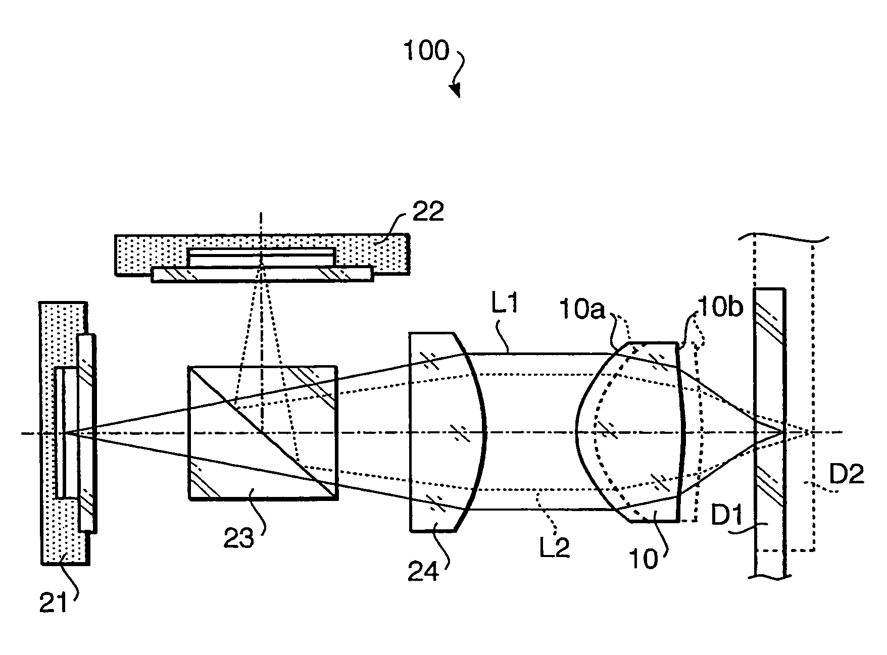
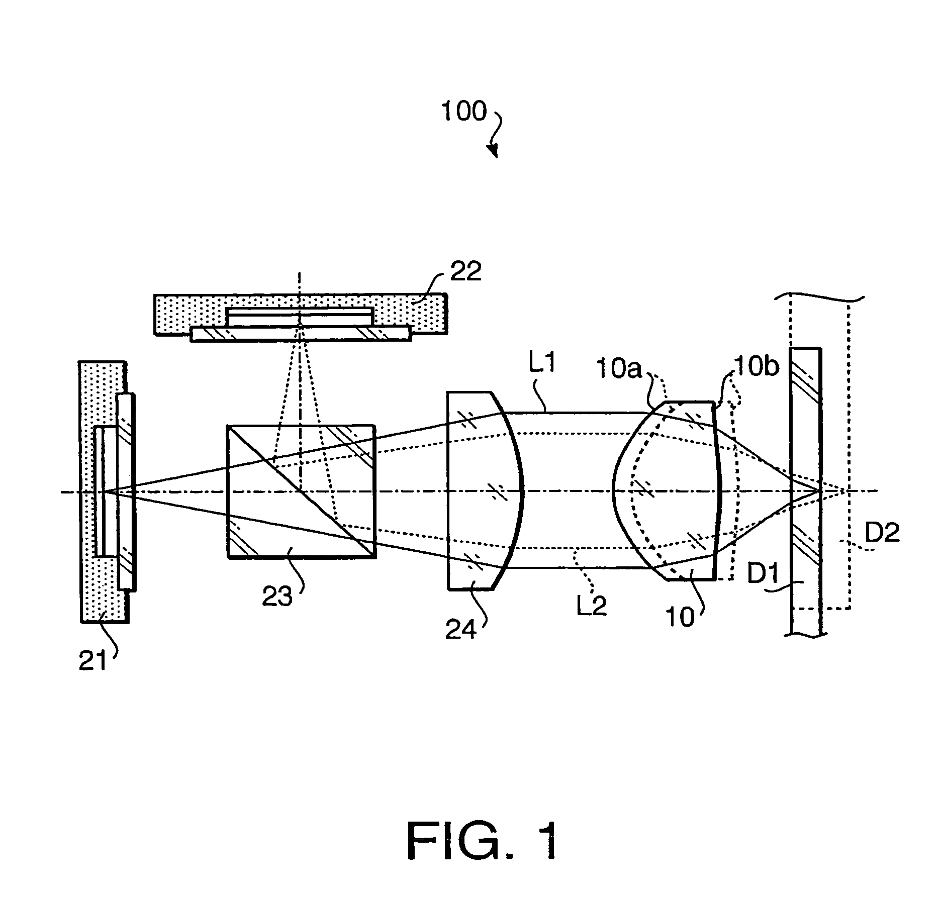
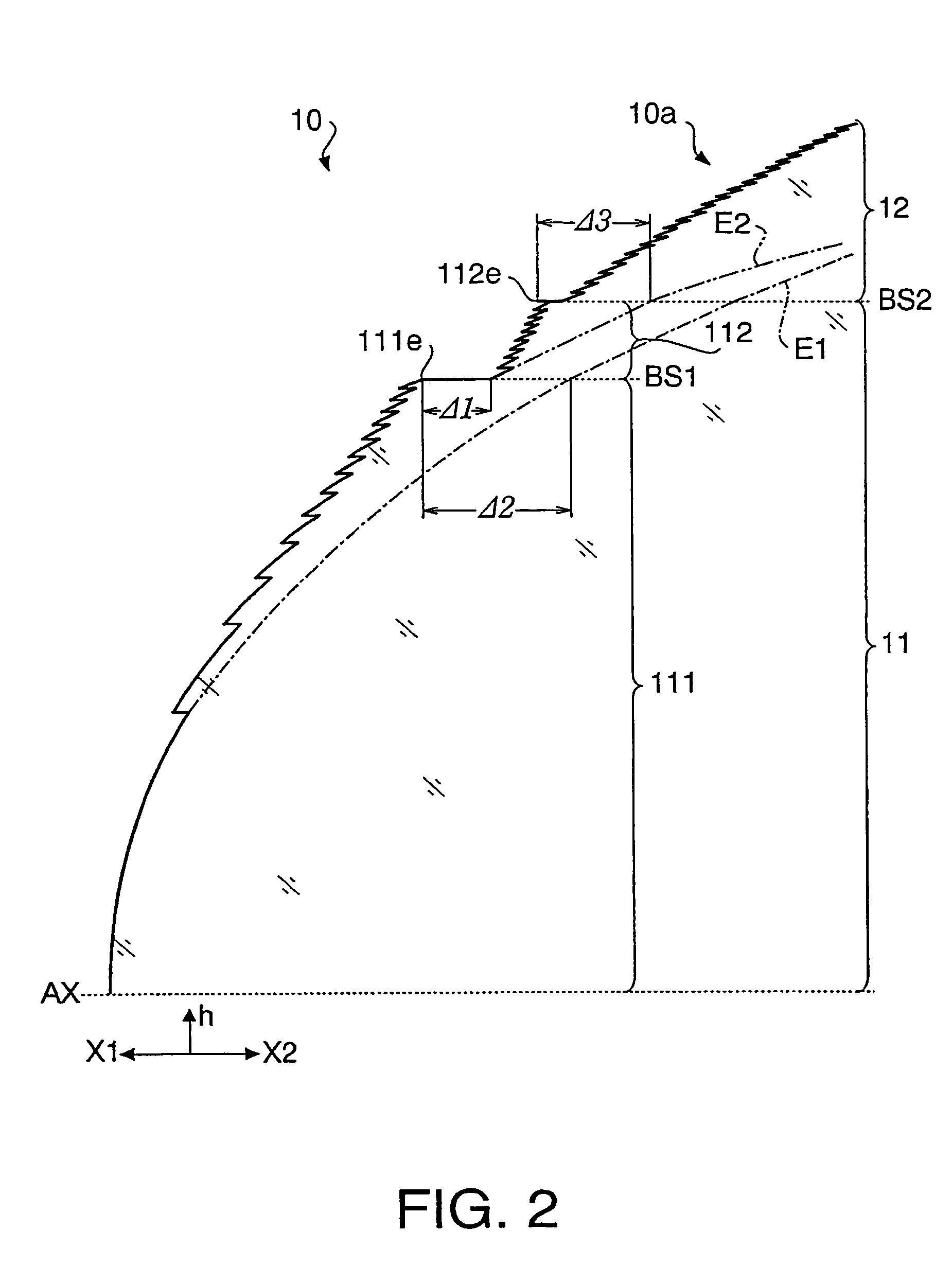
[0076]An optical system of the first example according to the embodiment will be explained below with reference to FIG. 1. FIG. 1 also shows the optical system 100 according to the first example. In the first example, the objective lens 10 is a single-element objective lens, and the surface 10a is provided with a minute step structure having a plurality of steps. The surface 10b of the objective lens 10 is a rotationally-symmetrical aspherical surface. Table 1 shows optical performance of the objective lens 10. Table 2 shows a numerical configuration of the optical system 100 according to the first example.

[0077]

TABLE 1DVDCDM0.000.00f (mm)3.003.02Design wavelength (nm)660785design NA0.650.53

[0078]In Table 1, M and f represent the magnification and the focal length of the objective lens 10, respectively. Design wavelength means that a wavelength of light suitable for the recordation / reproduction for each optical disc. In this example, the design wavelength for the disc D1 (DVD) is 66...


PUM

PropertyMeasurementUnit
wavelengthaaaaaaaaaa
thicknessaaaaaaaaaa

Abstract

An objective lens for recording data to and / or reproducing data from first and second optical discs. The objective lens is provided with at least one surface including a plurality of annular zones divided by steps. The steps has functions of phase shifting a wavefront of light passing through the plurality of annular zones so that a beam spot formed at a converging point of an average wavefront of the wavefront phase shifted by the steps is used for the first and second optical discs. The plurality of annular zones of the at least one surface includes at least one annular zone structure which includes first and second annular zone groups, each of which has at least three steps for phase shifting the wavefront in a first direction, and a first return step which is a step formed at a boundary between the first and second annular zone groups. The first return step phase shifts the wavefront in a second direction opposite to the first direction. An absolute value |Δψ1| of a phase shifting amount of the first light beam given by the first return step satisfies a condition: 6π<|Δψ1|<14π . . . (1). The absolute value |Δψ1| of the phase shifting amount of the first light beam given by the first return step is smaller than larger one of an absolute value of a sum of phase shift amounts given by the first annular zone group and an absolute value of a sum of phase shift amounts given by the second annular zone group.

Description

BACKGROUND OF THE INVENTION[0001]The present invention relates to an objective lens for an optical disc drive, which is capable of recording data to and / or reproducing data from two types of optical discs having different thicknesses of cover layers and / or different recording densities.[0002]In general, an optical pick-up for an optical disc drive is provided with a laser source such as a laser diode, an objective lens which converges the laser beam emitted by the laser source on a recording surface of the optical disc to form a beam spot on the recording surface, and a signal detecting system that receives the laser beam which is reflected from the recording surface and passes through the objective lens. The signal detecting system produces various signals based on the received laser beam.[0003]There are various types of optical discs having different thicknesses of cover layers and / or different recording densities. For example, a DVD (digital versatile disc) has a recording densit...

Claims


Application Information

Patent Timeline
Patent Type & Authority Patents(United States)
IPC IPC(8): G11B7/00G02B13/00G02B3/08G02B13/18G11B7/135G11B7/1353G11B7/1367G11B7/1374G11B7/1392
CPCG11B7/1353G11B7/1367G11B7/13922G11B7/1374G11B2007/0006G02B13/00
Inventor TAKEUCHI, SHUICHIMARUYAMA, KOICHIKOREEDA, DAISUKE
Owner HOYA CORP
Why Eureka
Try Eureka