Two-stage variable-gain mixer employing shunt feedback

a variable-gain, mixer technology, applied in the field of mixers and demodulators, can solve the problems of high noise figure, inability to simultaneously achieve all three objectives, and the feedback circuit disclosed in both patents does not provide a single-ended input controlled impedance, so as to achieve the effect of increasing noise figure (nf) and increasing power consumption

Inactive Publication Date: 2006-04-25
IBM CORP
View PDF11 Cites 30 Cited by
  • Summary
  • Abstract
  • Description
  • Claims
  • Application Information

AI Technical Summary

Benefits of technology

[0008]At least one presently preferred embodiment of the present invention broadly embraces a two-stage mixer or demodulator employing shunt feedback to linearize the first stage and having a provision for adjusting the gain of the second stage. This two-stage approach allows the linearity as characterized by the input second-order intercept point (IIP2) and input third-order intercept point (IIP3) to be increased without substantially increasing the noise figure (NF) or unduly increasing the power consumption. This two-stage mixer or demodulator could be included, for example, as part of the radio-frequency (RF) front end of a cellular telephone handset.
[0009]Among the unique features associated with at least one embodiment of the present invention is the manner in which shunt feedback is used to provide low second-order and third-order nonlinearities along with low noise and a controlled impedance single-ended input. The use of shunt feedback also indirectly enables the use of variable gain in the mixer by controlling input impedance.

Problems solved by technology

High linearity, low noise, and low power are conflicting design requirements, and it is difficult to simultaneously achieve all three objectives.
Numerous conventional efforts deal with the issue of mixer linearity, because it is such an important issue in radio design.
The feedback circuits disclosed in both patents s do not provide a controlled impedance single-ended input.
The primary disadvantage of these circuits is high noise figure, and there is also no easy way to apply variable gain.

Method used


Image

  • Two-stage variable-gain mixer employing shunt feedback
  • Two-stage variable-gain mixer employing shunt feedback
  • Two-stage variable-gain mixer employing shunt feedback

Examples


Embodiment Construction

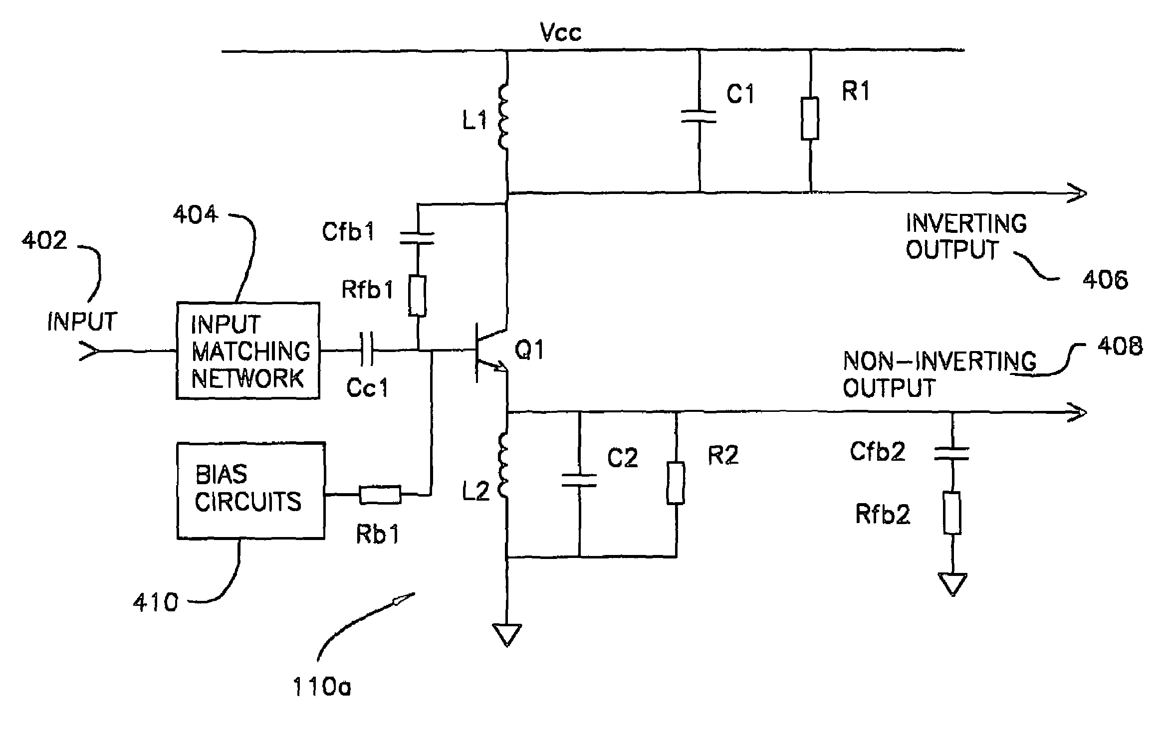
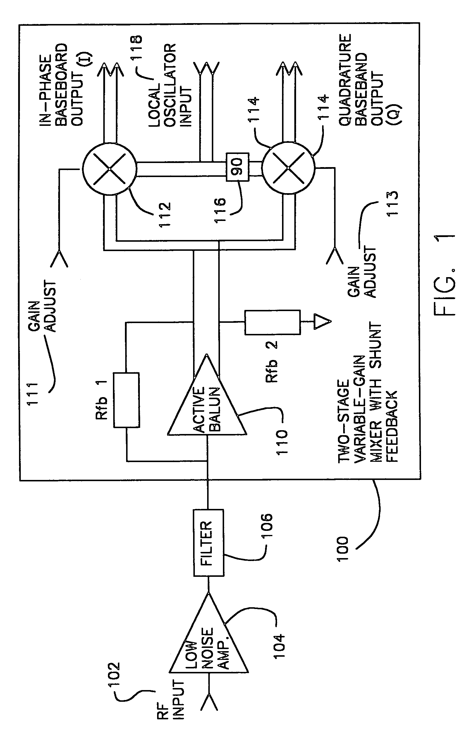
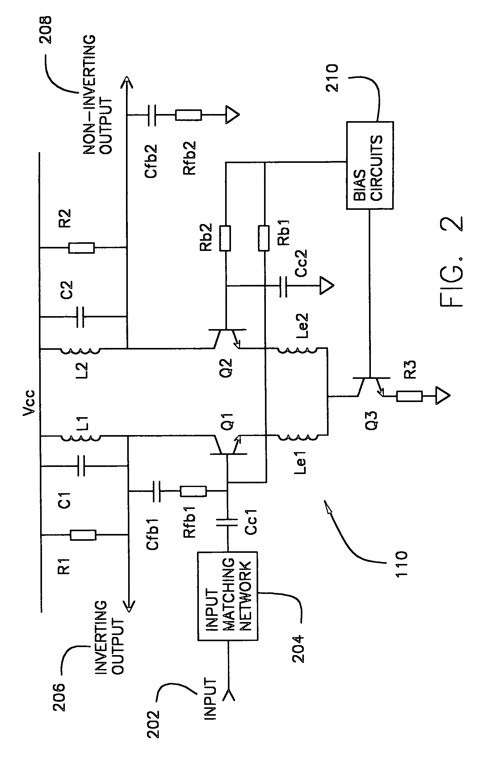
[0016]A block diagram of a two-stage demodulator is shown in FIG. 1, as it would typically be used in the radio-frequency (RF) front end of a cellular telephone handset. The demodulator 100 preferably accepts a single-ended RF signal input 102 from a band-select filter 106, which may typically be an off-chip mechanical filter, such as a SAW filter. As a design requirement, the demodulator may preferably present a particular input impedance (50 ohms in the present example) as a load for the filter, in order that the filter performs properly; this may be accomplished by designing the active balun 110 to provide a stable 50 ohm input impedance over the frequency range of interest, and by designing Low Noise Amplifier 104 to have a stable 50 ohm output impedance over the frequency range of interest. Preferably, an active balun circuit 110 with negative shunt feedback (Rfb1 and Rfb2) both amplifies the signal and converts it to differential form. The differential RF signal from the activ...


PUM


Abstract

A demodulator which includes an active balun circuit and at least one mixer driven by the active balun circuit. The active balun circuit includes a negative shunt feedback arrangement.

Description

FIELD OF THE INVENTION[0001]The present invention relates, generally, to mixers and demodulators in various radio architectures.BACKGROUND OF THE INVENTION[0002]In direct-conversion or low-intermediate-frequency radio architectures, such as are commonly used for Wideband Code Division Multiplex Access (WCDMA) band and multi-band cellular telephones, stringent requirements are placed on linearity in the receive signal path. Specifically, the receive signal path should desirably generate very low second-order and third-order intermodulation products while still achieving low noise figure and consuming low power. High linearity, low noise, and low power are conflicting design requirements, and it is difficult to simultaneously achieve all three objectives.[0003]Numerous conventional efforts deal with the issue of mixer linearity, because it is such an important issue in radio design. The use of emitter degeneration is common. Two-stage designs are also commonly used to achieve a better...

Claims


Application Information

Patent Timeline
Patent Type & Authority Patents(United States)
IPC IPC(8): H04B1/26H03D7/14H03F3/45H03H11/32H04B1/28
CPCH03D7/1433H03H11/32H04B1/28H03D7/145H03D7/1491H03D7/165H03F3/45085H03D2200/0025H03F2200/372H03F2203/45306H03F2203/45386H03F2203/45492H03F2203/45702H03F2203/45704H03D2200/0023
Inventor REYNOLDS, SCOTT K.
Owner IBM CORP
Why Eureka
Try Eureka