Self aligned magnetoresistive flux guide read head with exchange bias underneath free layer

a self-aligning magnetoresistive flux and read head technology, applied in the field of magnetoresistive sensors, can solve the problems of reducing read sensitivity and losing hard biasing effectiveness relative to the free layer

Inactive Publication Date: 2006-05-02
HITACHI GLOBAL STORAGE TECH NETHERLANDS BV
View PDF29 Cites 23 Cited by
  • Summary
  • Abstract
  • Description
  • Claims
  • Application Information

AI Technical Summary

Problems solved by technology

A disadvantage of the read head of the '547 patent is that the flux guide and the sensing element structures are defined by separate photo processing operations, and the flux guide has a track width which is narrower than that of the sensing element.
It is believed that this reduces read sensitivity because the magnetic flux carried from the narrower track width of the flux guide into the wider track width of the sensing element device becomes diluted.
Another disadvantage of the read head of the '547 patent stems from the use of hard biasing material to longitudinally bias the sensing element free layer for noise reduction and improvement of signal-to-noise characteristics.
Unfortunately, the required insulating thickness is sufficiently large that hard biasing effectiveness relative to the free layer is lost.

Method used


Image

  • Self aligned magnetoresistive flux guide read head with exchange bias underneath free layer
  • Self aligned magnetoresistive flux guide read head with exchange bias underneath free layer
  • Self aligned magnetoresistive flux guide read head with exchange bias underneath free layer

Examples


Embodiment Construction

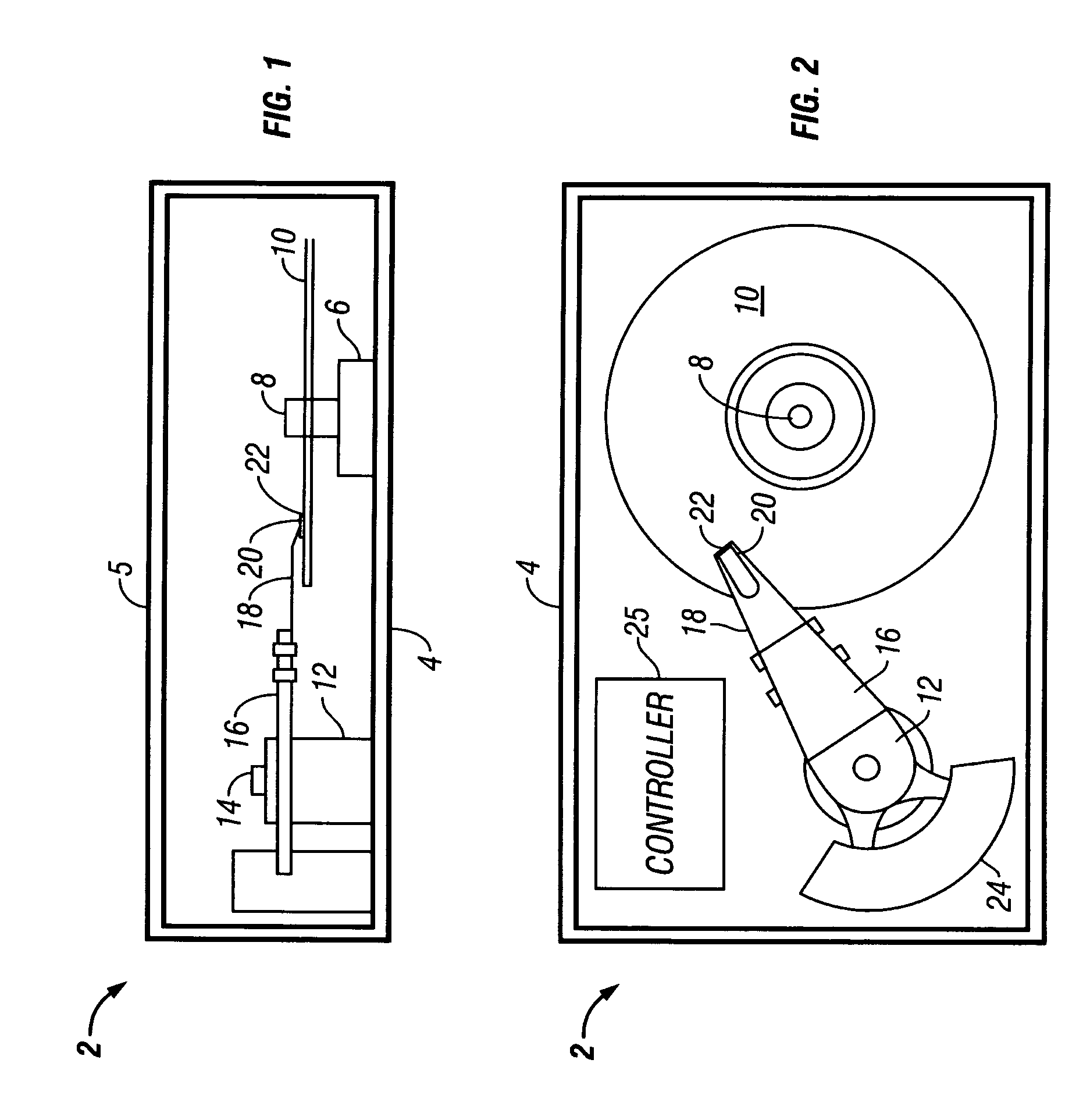
[0039]Turning now to the figures, wherein like reference numerals represent like elements in all of the several views, FIGS. 1 and 2 illustrate an exemplary disk drive 2 that incorporates a magnetoresistive sensor in accordance with the invention. Note that the disk drive 2 is shown in greatly simplified schematic form, with only those construction details that are necessary for an understanding of the invention being represented. As to these illustrated components, it should be understood that all are conventional in nature unless otherwise indicated below.

[0040]The disk drive 2 conventionally includes a base casting 4 made from cast aluminum or other suitable material. A cover 5 is removably mounted thereto via a hermetic seal (not shown). The base casting 4 mounts a conventional spindle drive motor 6 having an associated drive spindle 8. The drive spindle 8 carries a disk 10 for high speed rotation therewith. Other disks (not shown) may also be carried on the drive spindle 8 to f...


PUM

PropertyMeasurementUnit
thicknessaaaaaaaaaa
thicknessaaaaaaaaaa
thickaaaaaaaaaa

Abstract

A magnetoresistive sensor for use in a data storage device has a recessed sensing element (magnetic tunnel junction, CPP spin valve, etc.) with an exchange biased sensing ferromagnetic (free) layer, and a flux guide that magnetically connects the sensing element to a sensing surface of the sensor. The free layer is selectively exchange biased by a layer of exchange bias material placed under non-active regions of the free layer that lie outside the sensing element and flux guide track widths. The flux guide is provided by extending the free layer from a forward edge of the sensing element to the sensor surface. Advantageously, the sensing element and the flux guide have equal track width so that magnetic flux directed from the flux guide into the sensing element is not diluted with consequent loss of sensitivity.

Description

[0001]This application is a divisional of application Ser. No. 09 / 922,446, filed on Aug. 2, 2001, now U.S. Pat. No. 6,657,825.BACKGROUND OF THE INVENTION[0002]1. Field of the Invention[0003]The present invention relates to magnetoresistive sensors for reading magnetically-recorded information from data storage media, and particularly to MTJ (Magnetic Tunnel Junction and CPP (Current-Perpendicular-to-Plane) spin valve read sensors for direct access storage device (DASD) systems.[0004]2. Description of the Prior Art[0005]By way of background, MTJ and CPP spin valve devices have been proposed for use as magnetic field sensors (e.g., read head sensors) in DASD systems, such as disk drives. An MTJ sensor is a variable current device formed by a magnetically pinned ferromagnetic layer and a magnetically free ferromagnetic layer separated by an intervening tunnel barrier layer. The barrier layer is made from a material that is electrically insulating but thin enough to pass charge carriers...

Claims


Application Information

Patent Timeline
Patent Type & Authority Patents(United States)
IPC IPC(8): G11B5/127H04R31/00G11B5/39
CPCB82Y10/00B82Y25/00G11B5/3903G11B5/3909G11B5/3916Y10T29/49048Y10T29/49052Y10T29/49044Y10T29/49046Y10T29/49032Y10T29/49043
Inventor HO, KUOK SANPAN, TAO
Owner HITACHI GLOBAL STORAGE TECH NETHERLANDS BV
Why Eureka
Try Eureka