Novel CPP device with an enhanced dR/R ratio

a cpp device and enhanced technology, applied in the field of spacer layers, can solve the problems of em performance degradation, low mr ratio, etc., and achieve the effect of preventing undesirable barkhausen nois

Active Publication Date: 2008-11-13
HEADWAY TECH INC
View PDF11 Cites 65 Cited by
  • Summary
  • Abstract
  • Description
  • Claims
  • Application Information

AI Technical Summary

Benefits of technology

[0017]A spin valve stack that includes the composite spacer layer may be sputter deposited using Ar gas in a sputtering system that is equipped with an ultra-high vacuum. In the case of a metal oxide layer such as a ZnO layer, a metal layer may be formed first by sputter depositing Zn, and then oxidizing the metal layer by a plasma oxidation, radical oxidation (ROX), or natural oxidation (NOX) method. Optionally, a metal oxide layer may be sputter deposited. After the cap layer is deposited, the CPP-

Problems solved by technology

Unfortunately, the MR ratio is often very low (<5%) in many CPP-GMR spin valve structures involving metal spacers.
However, Fe rich CoFe alloys may cause EM performance degradation.
Althoug

Method used


Image

  • Novel CPP device with an enhanced dR/R ratio
  • Novel CPP device with an enhanced dR/R ratio

Examples


example 1

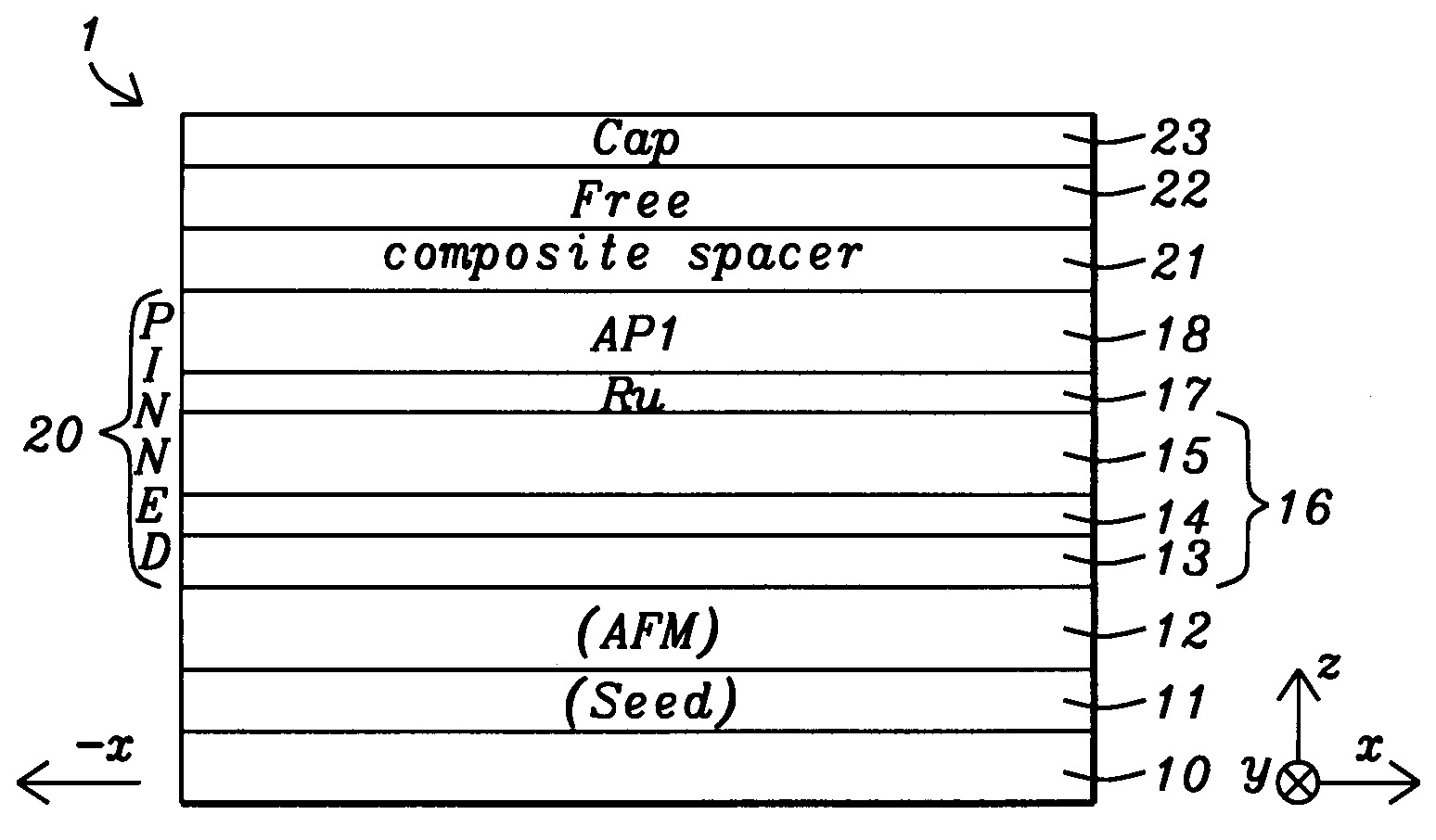
[0040]A bottom spin valve structure was formed having a composition represented by Ta10 / Ru10 / IrMn70 / Fe10Co9010 / Fe70Co3014 / Fe10Co9020 / Ru7.5 / Fe70Co3015 / Cu2 / Fe70Co3015 / Cu3 / ZnO15 / Cu3 / Fe70Co308 / CoFeB12 / Ni90Fe1060 / Cu30 / Ru10 / Ta60 / Ru30. Each value next to the individual layer indicates the film thickness in Angstroms. In the above structure, the following layers are formed successively on the substrate: seed layer (Ta / Ru); AFM layer (IrMn); AP2 (Fe10Co90 / Fe70Co30 / Fe10Co90); Ru coupling layer, AP1 (Fe70Co30 / Cu / Fe70Co30); composite spacer (Cu / ZnO / Cu); free layer (Fe70Co30 / CoFeB / Ni90Fe10), and capping layer (Cu / Ru / Ta / Ru). A dR / R=10.0% and a RA=0.092 ohm-um2 was measured for this device which is a substantial improvement over prior art CPP-GMR devices having a full film CPP design. This example represents an embodiment where the composite spacer layer has a M / S / M configuration in which M is Cu and S is ZnO.

example 2

[0041]A bottom spin valve structure was formed having a composition represented by Ta10 / Ru10 / IrMn70 / Fe10Co90 / Fe70Co3014 / Fe10Co9020 / Ru7.5 / Fe70Co3015 / Cu2 / Fe70Co3015 / ZnO8 / Cu2 / ZnO8 / Fe70Co308 / CoFeB12 / Ni90Fe1060 / Cu30 / Ru10 / Ta60 / Ru30. This example represents an embodiment where the composite spacer layer has a S / M / S configuration in which M is Cu and S is ZnO. A dR / R=17.0% and a RA=0.342 ohm-um2 was measured for this device which is a substantial improvement over prior art CPP-GMR devices having a full film CPP design.

example 3

[0042]A bottom spin valve structure was formed having a composition represented by Ta10 / Ru10 / IrMn70 / Fe10Co9010 / Fe70Co3014 / Fe10Co9020 / Ru7.5 / Fe70Co3015 / Cu2 / Fe70Co305 / Cu2 / ZnO8 / Cu2 / ZnO8 / Cu2 / Fe70Co308 / CoFeB12 / Ni90Fe1060 / Cu30 / Ru10 / Ta60 / Ru30. This example represents an embodiment where the composite spacer layer has a M / S / M / S / M configuration in which M is Cu and S is ZnO. Values for dR / R and RA have not been measured yet but an improvement is anticipated over spin valve structures comprised of a conventional Cu spacer layer based on the results from the first two examples.


PUM

PropertyMeasurementUnit
Fractionaaaaaaaaaa
Thicknessaaaaaaaaaa
Thicknessaaaaaaaaaa

Abstract

A CPP-GMR spin valve having a composite spacer layer comprised of at least one metal (M) layer and at least one semiconductor or semi-metal (S) layer is disclosed. The composite spacer may have a M/S, S/M, M/S/M, S/M/S, M/S/M/S/M, or a multilayer (M/S/M)n configuration where n is an integer ≧1. The pinned layer preferably has an AP2/coupling/AP1 configuration wherein the AP2 portion is a FCC trilayer represented by CoZFe(100-Z)/FeYCo(100-Y)/CoZFe(100-Z) where y is 0 to 60 atomic %, and z is 75 to 100 atomic %. In one embodiment, M is Cu with a thickness from 0.5 to 50 Angstroms and S is ZnO with a thickness of 1 to 50 Angstroms. The S layer may be doped with one or more elements. The dR/R ratio of the spin valve is increased to 10% or greater while maintaining acceptable EM and RA performance.

Description

RELATED PATENT APPLICATION[0001]This application is related to the following: Docket # HT05-015, Ser. No. 11 / 180,808, filing date Jul. 13, 2005; and Docket # HT05-038, Ser. No. 11 / 234,719, filing date Sep. 23, 2005; both assigned to a common assignee, both of which are herein incorporated by reference in their entirety.FIELD OF THE INVENTION[0002]The invention relates to a spacer layer for use in a giant magnetoresistive (GMR) sensor in a current perpendicular to plane (CPP) magnetic read head and in particular to a composite spacer comprised of at least one metal layer and one semiconductor or semi-metal layer that provides an improved magnetoresistive (MR) ratio.BACKGROUND OF THE INVENTION[0003]A magnetic disk drive includes circular data tracks on a rotating magnetic disk and read and write heads that may form a merged head attached to a slider on a positioning arm. During a read or write operation, the merged head is suspended over the magnetic disk on an air bearing surface (AB...

Claims


Application Information

Patent Timeline
IPC IPC(8): G11B5/127
CPCB82Y10/00B82Y25/00G11B2005/3996G11B5/3909G11B5/3906Y10T29/49039Y10T29/49043Y10T29/49044
Inventor ZHANG, KUNLIANGLI, MINDOVEK, MORISLIU, YUE
Owner HEADWAY TECH INC
Why Eureka
Try Eureka