Novel process and structure to fabricate CPP spin valve heads for ultra-hing recording density

a technology of ultra-hing and valve head, which is applied in the field of new process and structure to fabricate cpp spin valve head for ultra-hing recording density, can solve the problems of limiting the operating frequency, johnson and shot noise, and the mr ratio but has limitations, so as to improve the specular reflection and increase the bulk scattering

Inactive Publication Date: 2005-09-15
HEADWAY TECH INC
View PDF11 Cites 70 Cited by
  • Summary
  • Abstract
  • Description
  • Claims
  • Application Information

AI Technical Summary

Benefits of technology

[0024] In a second embodiment, a dual spin valve with two AFM layers and one free layer is constructed by employing the sputtering method of the present invention. The structure of the first embodiment is followed through the formation of the copper spacer. In this case, the free layer formed on the copper spacer is preferably comprised of a bottom CoFe layer, a middle NiFe layer, and an upper CoFe layer. The middle NiFe layer may be comprised of an insertion layer. Next, a second copper spacer is formed on the free layer followed by a second oxygen surfactant layer (OSL) on the second copper spacer. A second synthetic pinned layer is then deposited and includes a second Ru coupling layer sandwiched between an AP3 CoFe layer on the second OSL and an upper AP4 CoFe layer. The AP3 layer may be further comprised of a nano-oxide layer (NOL) or a dusting layer that separates top and bottom portions of the CoFe layer to improve specular reflection. In this embodiment, both the AP2 and AP4 layers do not contain an oxygen dopant. A second AFM layer is deposited on the AP4 layer followed by a Ta capping layer to complete the dual spin valve structure. The sensor stack comprised of the dual spin valve structure is annealed and then the remainder of the read head is fabricated. For example, the second magnetic shield layer (S2) is typically used as the top conductor lead layer in a CPP spin valve. The second embodiment also encompasses thicker layers in the stack to increase bulk scattering.

Problems solved by technology

Bulk scattering in thicker magnetic layers improves the MR ratio but has limitations because a larger sensor size will affect the output voltage.
However, the TMR head has several disadvantages of which one is a large resistance that limits the operating frequency and makes the Johnson and shot noise high.
It is considered too difficult to reduce TMR head resistance without a breakthrough in fabrication technology for low resistance barrier layers.
However, the resistance (RA) in a conventional single spin valve is too small (2) and the MR ratio of a CPP head is very low (<0.5%).
Additionally, the output voltage which is related to the resistance change is too low.

Method used


Image

  • Novel process and structure to fabricate CPP spin valve heads for ultra-hing recording density
  • Novel process and structure to fabricate CPP spin valve heads for ultra-hing recording density

Examples


first embodiment

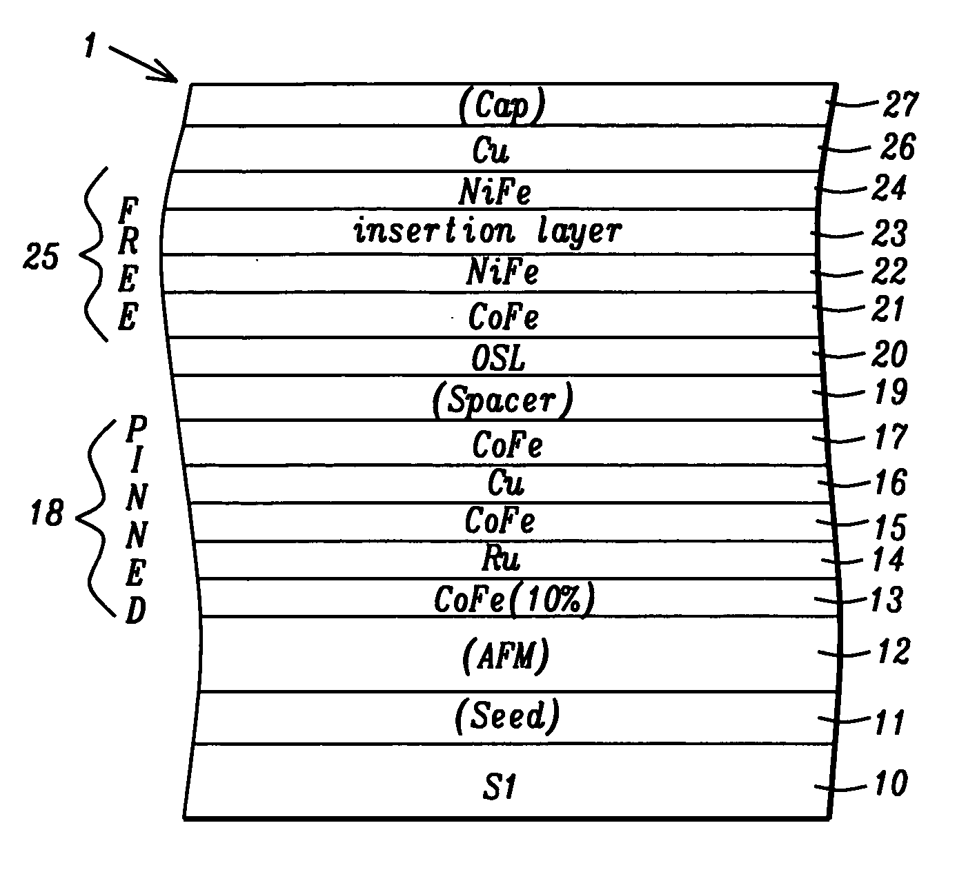
[0027] The present invention is a CPP-GMR spin valve structure for a sensor in a read head of a magnetic recording device and a method for making the same. The spin valve structure is especially suited for an ultra-high magnetic recording device wherein the recording density is greater than about 100 Gbits / in2. The drawings are provided by way of example and are not intended to limit the scope of the invention. Although a bottom spin valve structure is described in the first embodiment, those skilled in the art will appreciate that the sputtering method of the present invention is equally applicable to forming a top spin valve structure. Moreover, the invention encompasses both single and dual spin valve structures.

[0028] A first embodiment is set forth in FIG. 1 in which a sensor comprised of a bottom CPP-GMR spin valve structure is illustrated. The inventors have found that magnetic layers doped with a small amount of oxygen significantly enhance the MR ratio of the spin valve ele...

second embodiment

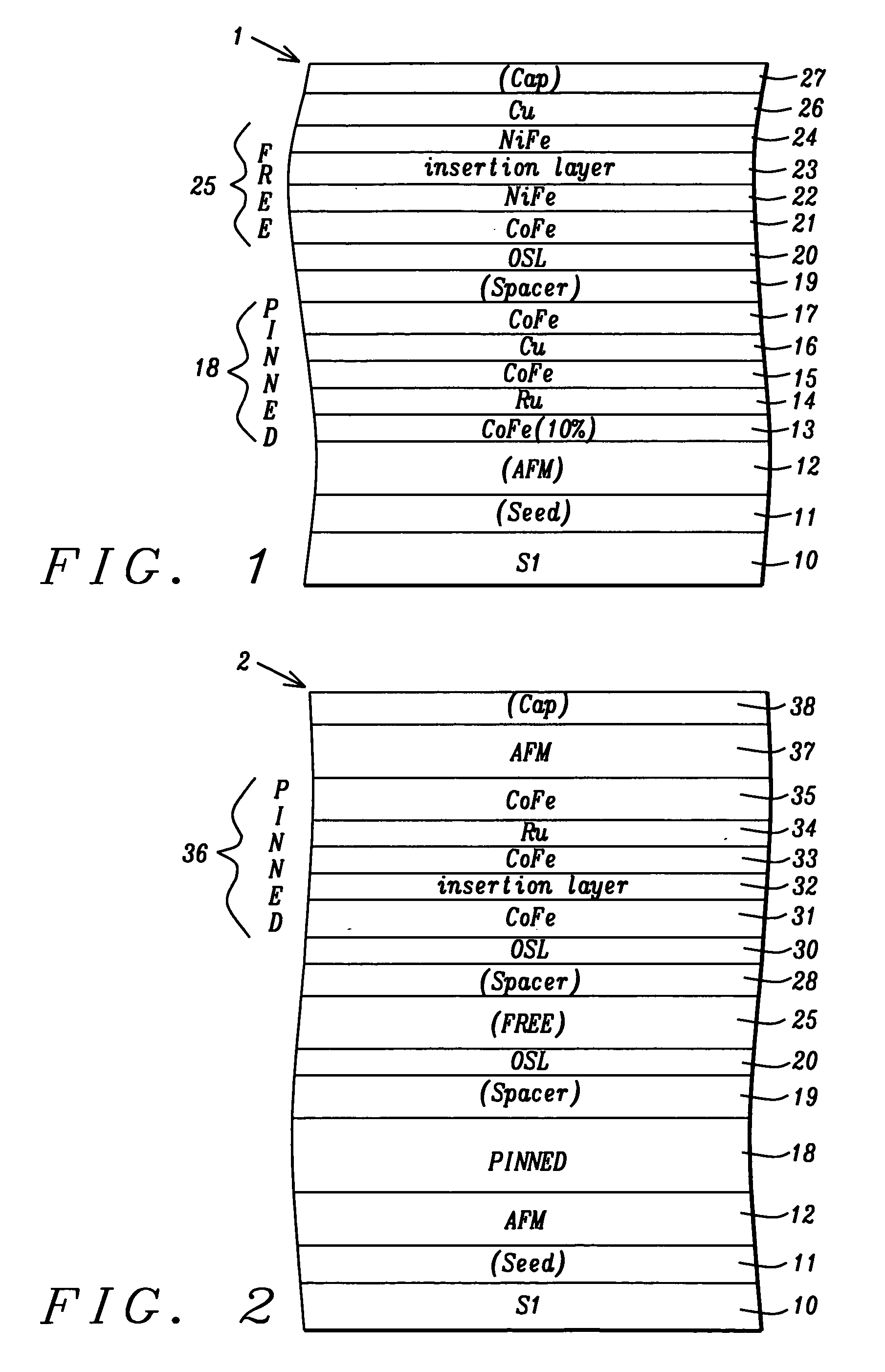
[0041] In a second embodiment, a dual CPP-GMR spin valve structure is formed as depicted in FIG. 2. Although a dual SyAP pinned spin valve is illustrated, a key feature of the present invention which is oxygen doped pinned, free, and AFM layers is also applicable to other types of dual spin valves as appreciated by those skilled in the art.

[0042] Referring to FIG. 2, the bottom portion of the dual spin valve structure 2 includes a majority of the layers in the spin valve described in the first embodiment. In particular, the stack comprised of a seed layer 11, a first AFM layer 12, a first SyAP pinned layer 18, copper spacer 19, and oxygen surfactant layer (OSL) 20 on the substrate 10 is part of a first spin valve in the CPP dual spin valve structure 2.

[0043] A second spin valve stack formed above the first spin valve will now be described. The combination of the second spin valve and the first spin valve form the preferred dual CPP-GMR sensor of the present invention. It is underst...


PUM

PropertyMeasurementUnit
pressureaaaaaaaaaa
partial pressureaaaaaaaaaa

Abstract

A CPP-GMR spin value sensor structure with an improved MR ratio and increased resistance is disclosed. All layers except certain pinned layers, copper spacers, and a Ta capping layer are oxygen doped by adding a partial O2 pressure to the Ar sputtering gas during deposition. Oxygen doped CoFe free and pinned layers are made slightly thicker to offset a small decrease in magnetic moment caused by the oxygen dopant. Incorporating oxygen in the MnPt AFM layer enhances the exchange bias strength. An insertion layer such as a nano-oxide layer is included in one or more of the free, pinned, and spacer layers to increase interfacial scattering. The thickness of all layers except the copper spacer may be increased to enhance bulk scattering. A CPP-GMR single or dual spin valve of the present invention has up to a threefold increase in resistance and a 2 to 3% increase in MR ratio.

Description

FIELD OF THE INVENTION [0001] The invention relates to processes and materials used in the fabrication of a giant magnetoresistive (GMR) sensor in a magnetic read head and in particular to a sputtering process for depositing all of the magnetic layers in a sensor stack having a current-perpendicular-to-plane (CPP) configuration. BACKGROUND OF THE INVENTION [0002] A magnetic disk drive includes circular data tracks on a rotating magnetic disk and read and write heads that may form a merged head attached to a slider on a positioning arm. During a read or write operation, the merged head is suspended over the magnetic disk on an air bearing surface (ABS). The sensor in a read head is a critical component since it is used to detect magnetic field signals by a resistance change. One form of magnetoresistance is a spin valve magnetoresistance (SVMR) or giant magnetoresistance (GMR) which is based on a configuration in which two ferromagnetic layers are separated by a non-magnetic conducti...

Claims


Application Information

Patent Timeline
Patent Type & Authority Applications(United States)
IPC IPC(8): G11B5/127G11B5/33G01R33/09G11B5/39H01F10/16H01F10/32H01F41/18H01F41/30H01L43/08H01L43/12
CPCB82Y25/00B82Y40/00G11B5/3906G11B5/3948H01F10/3259H01F10/3272H01F41/306H01L43/08H01L43/12H01F10/3263H10N50/85H10N50/10H10N50/01
Inventor HORNG, CHENG T.TONG, RU-YING
Owner HEADWAY TECH INC
Why Eureka
Try Eureka