

Solvent extraction of a halide from a aqueous sulphate solution
a technology of aqueous sulphate and solvent, applied in the field of extraction of halides, can solve problems such as hygiene problems
- Summary
- Abstract
- Description
- Claims
- Application Information
AI Technical Summary
Problems solved by technology
Method used
Image

Examples
Embodiment Construction
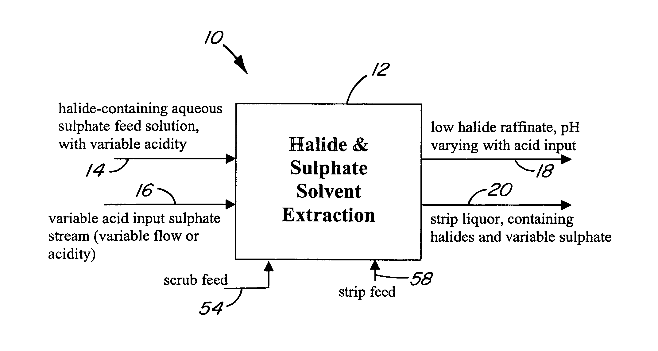
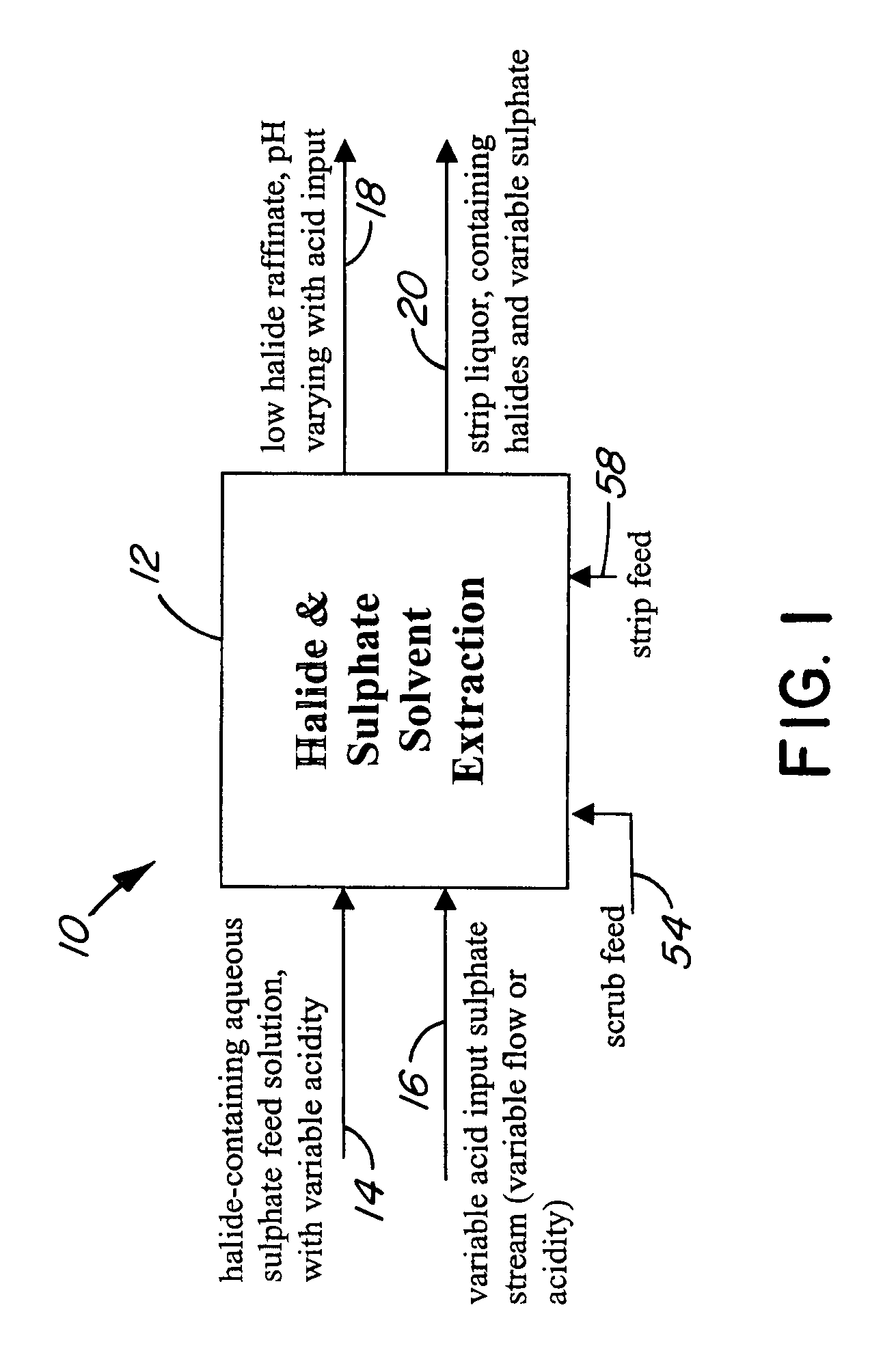
[0029]FIG. 1 is a general representation of a halide and sulphate extraction process 10. The process 10 comprises a halide and sulphate solvent extraction 12 which has as its input a halide-containing aqueous sulphate feed solution 14 and an acidic sulphate solution 16. The solutions 14 and 16 can be mixed prior to being subjected to the solvent extraction 12.
[0030]In practice, the total acidity of the combined solutions 14 and 16 varies from a relatively high acid content (low pH) to a relatively low acid content, i.e. the solution is practically neutral.
[0031]In carrying out the process 10, the total acidity of the solutions 14 and 16 and / or the flow rate of the acidic sulphate solution 16 is varied to provide a low halide raffinate 18 and a strip liquor 20 as output from the solvent extraction 12. The low halide raffinate 18 has a varying pH and sulphate content depending on the total acidity of the solutions 14 and 16. The strip liquor 20 has a varying sulphate content also depe...
PUM
| Property | Measurement | Unit |
|---|---|---|
| pH | aaaaa | aaaaa |
| extraction efficiency | aaaaa | aaaaa |
| temperature | aaaaa | aaaaa |
Abstract
Description
Claims
Application Information