
Retinal treatment method

a retinal treatment and treatment method technology, applied in the field of retinal treatment methods, can solve the problems of no devices or compositions, and achieve the effects of promoting retinal traction, reducing the distance between the substance and its target, and enhancing the stimulation

Inactive Publication Date: 2006-05-02
PIXIUM VISION SA
View PDF77 Cites 30 Cited by
  • Summary
  • Abstract
  • Description
  • Claims
  • Application Information

AI Technical Summary

Benefits of technology

[0011]The inventive method takes advantage of the physiological placement of the internal limiting membrane in the eye. Previous surgical implant methods had removed the internal limiting membrane. However, the inventive method not only retains the internal limiting membrane, but also takes advantage of the space between it and the adjacent retinal layers to implant a therapeutic or preventative substance. In this way, non-physiological mechanical or chemical fasteners are not needed to locate and secure the implanted substance in place. Thus, there are no devices or compositions which may cause bleeding from the choroid or which may promote retinal traction originating from the cells migrating from the choroid through the mechanical pins, both of which are problems in current methods.
[0012]Another improvement using the inventive method is that the substance implanted is in direct contact with the neurofiber layer and ganglion cells of the retina. This advantageously enhances their stimulation, since the distance between the substance and its target is decreased. For example, when electrical arrays are implanted, there is enhanced qualitative and quantitative cell stimulation because the stimulus is close enough to reach ganglion cells and the neurofiber layer that is located a distance of about 10-50 μm away.
[0013]Still anther improvement is that the inventive method eliminates the need for external stimulation, as is used with currently available diode arrays.

Problems solved by technology

Thus, there are no devices or compositions which may cause bleeding from the choroid or which may promote retinal traction originating from the cells migrating from the choroid through the mechanical pins, both of which are problems in current methods.

Method used


Image

  • Retinal treatment method

Examples


Embodiment Construction

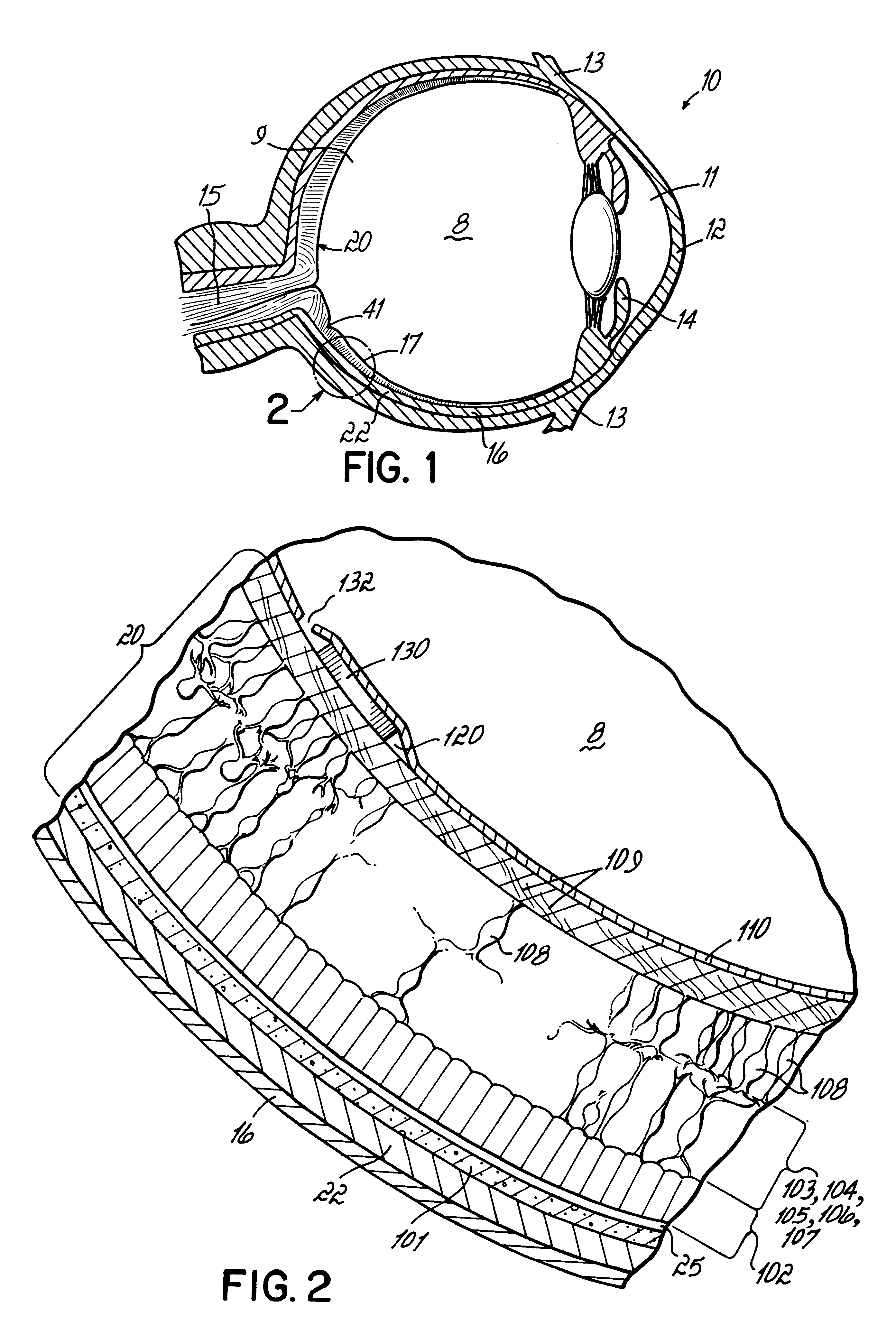
[0017]With reference to FIG. 1, a mammalian eye 10 is shown. The locations of the vitreous cavity 8, posterior chamber 9, anterior chamber 11, cornea 12, conjunctiva 13, iris 14, optic nerve 15, sclera 16, macula lutea 17, lens 18, retina 20, ora serrata 21, and choroid 22 are illustrated.

[0018]The most sensitive portion of the retina 20 is the macula lutea 17, which is located in the center of the posterior part of the retina 20. The inner surface of the retina 20, near the border of the optic nerve 15, has a shallow round depression, the fovea 41. The fovea 41 is surrounded by the central area, distinguished by the great number of ganglion cells and by the general refinement and even distribution of the structural elements, especially the rod cells and the cone cells. About one-tenth inch inside the fovea 41 is the point of entrance of the optic nerve 15 and its central artery. At this point, the retina 20 is incomplete and forms the blind spot.

[0019]With reference to FIG. 2, the ...


PUM

PropertyMeasurementUnit
Cell angleaaaaaaaaaa
Biocompatibilityaaaaaaaaaa
Lightaaaaaaaaaa

Abstract

A method for treating or preventing retinal pathology or injury. The method locates and secures a retinal stimulating substance in the eye between the internal limiting membrane and the retina, which is the target site for the substance. The substance may be an implant that provides electrical stimulation to adjacent ganglion and neurofiber cells. Alternatively, the substance may be a pharmaceutical substance to stimulate the retina. In addition to providing direct contact of the substance with its target, the method obviates the need for artificial structures such as tacks or adhesives which may cause retinal bleeding or traction.

Description

FIELD OF THE INVENTION[0001]The invention relates to methods for providing a device or composition to a retina.BACKGROUND OF THE INVENTION[0002]The retina is the innermost layer of the wall of the eyeball located in the posterior segment of the eye. Developed as an outgrowth from the brain, the retina contains nervous tissue, specifically, light-sensitive cells (photoreceptors) and complex neural networks. These networks provide visual information and send impulses through the optic nerve to the brain.[0003]Degenerative diseases of the retina, such as retinitis pigmentosa, age-related macular degeneration, and hereditary retinal degenerations cause degeneration and death of the photoreceptor cells, resulting in decreased visual function. Fortunately, even in end-stage disease, numerous neuronal cells in the inner retina survive. However, because of loss of the photoreceptors, light stimulation does not occur and the neuronal cells must be artificially stimulated to restore some degr...

Claims


Application Information

Patent Timeline
IPC IPC(8): A61K31/135A61F9/00A61K9/00A61N1/36A61N5/06
CPCA61F9/0017A61K9/0051A61N1/36046Y10S514/912A61N2005/0652
Inventor PEYMAN, GHOLAM
Owner PIXIUM VISION SA
Learn More