

Spiral cable device
a spiral cable and cable technology, applied in the direction of flat/ribbon cables, insulated conductors, cables, etc., can solve the problem of axial length of spiral cable devices to be enlarged, and achieve the effect of small width of flexible flat cabl
- Summary
- Abstract
- Description
- Claims
- Application Information
AI Technical Summary
Benefits of technology
Problems solved by technology
Method used
Image

Examples
first embodiment
(First Embodiment)
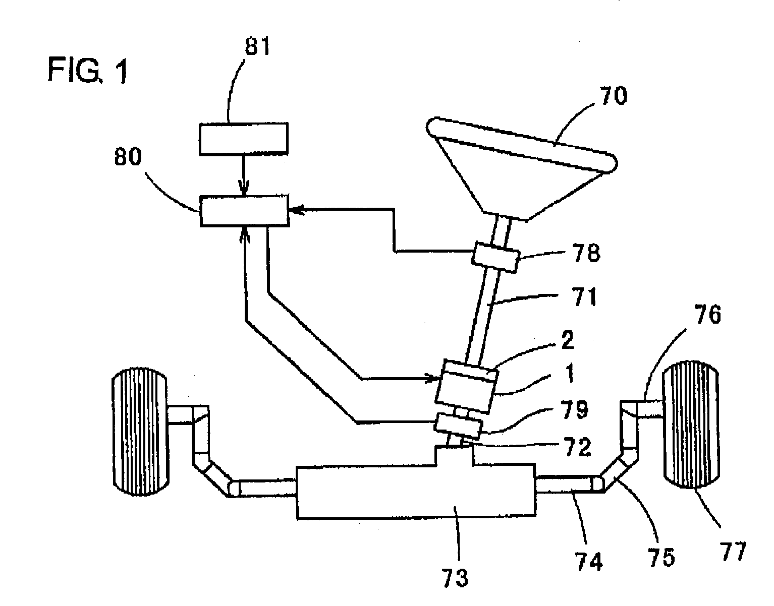
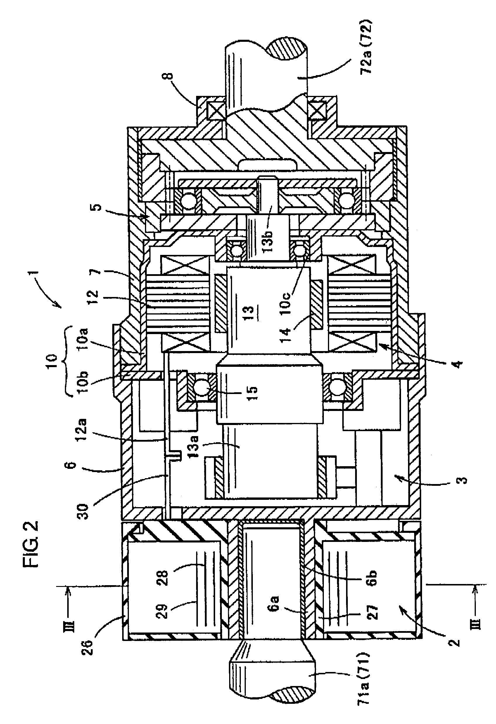
[0022]A spiral cable device in the first embodiment embodies the first invention and is employed in a variable gear ratio steering device 1 of a steering system shown in FIG. 1. The steering system includes a steering wheel or handle 70 which is connected to the upper end of an upper steering shaft 71 constituting an input shaft, through a constant velocity joint (not shown). The lower end of the upper steering shaft 71 is connected to the upper end of a lower steering shaft 72 constituting an output shaft, through the variable gear ratio steering device 1. The lower end of the lower steering shaft 72 is provided through another constant velocity joint (not shown) with a pinion (not shown), which is in meshing engagement with a rack shaft 74 within a steering gear box 73. Opposite ends of the rack shaft 74 are connected to respective one ends of tie rods, whose other ends are connected to steered road wheels 77 through knuckle arms 76, respectively.
[0023]Further, t...
second embodiment
(Second Embodiment)
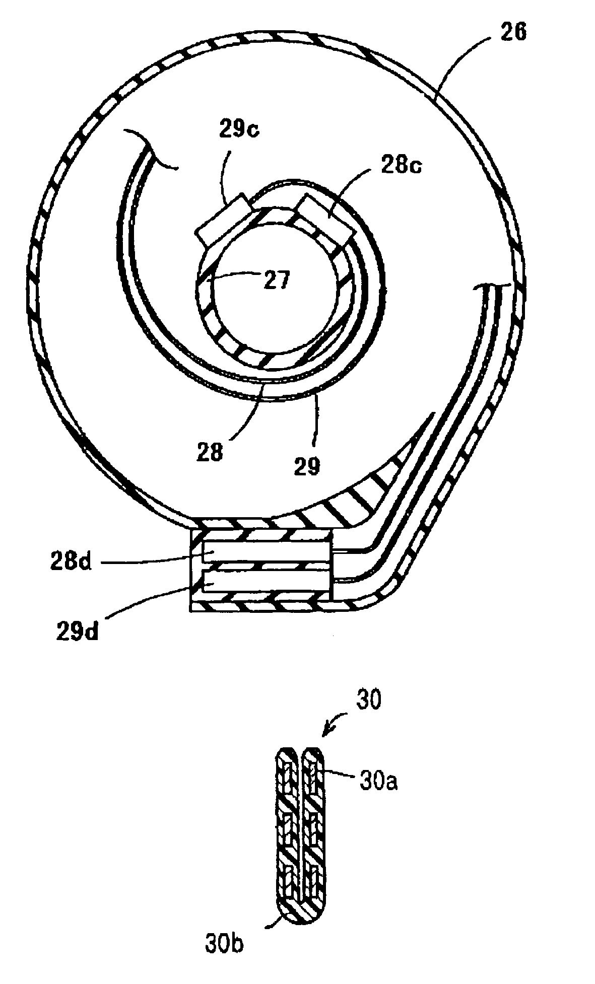
[0031]A spiral cable device in the second embodiment embodies the second invention. In the spiral cable device of the second embodiment, as shown in FIG. 4, there is employed a flexible flat cable 30, wherein plural leads 30a are arranged in a single layer and are coated to be isolated electrically by means of a PET film 30b having flexibility, and the flexible flat cable 30 is folded to be radially doubled within the cylindrical casing 26. That is, the cable 30 is folded to form multiple layers of the leads 30a. Other configurations of the second embodiment are the same to those in the first embodiment.
[0032]In the spiral cable device, the flexible flat cable 30 is folded to be radially doubled, i.e., to form multiple layers of the leads 30a. This makes small the width which the flexible flat cable 30 occupies within the cylindrical casing 26 in the axial direction of the same. Consequently, the cylindrical casing 26 can be made small in the axial direction, and ...
third embodiment
(Third Embodiment)
[0033]A spiral cable device in the third embodiment embodies the third invention. In the spiral cable device of the third embodiment, as shown in FIG. 5, there is employed a flexible flat cable 31, wherein plural leads 31a are arranged in two layers and are coated to be isolated electrically by means of a PET film 31b having flexibility. Other configurations of the second embodiment are the same to those in the first embodiment.
[0034]In the spiral cable device, since the flexible flat cable 31 has the plural leads 31a arranged in the two layers in the radial direction, the number of the leads which are arranged in each layer in the axial direction of the spiral cable device 2 can be reduced to the half compared with that in the prior art device wherein all the leads are arranged in a single layer, whereby the width of the flexible flat cable 31 can be made small. Consequently, the cylindrical casing 26 can be made small in the axial direction, and thus, the cable d...
PUM
| Property | Measurement | Unit |
|---|---|---|
| flexible | aaaaa | aaaaa |
| width | aaaaa | aaaaa |
| axial length | aaaaa | aaaaa |
Abstract
Description
Claims
Application Information