
Contact switch for high frequency application

a high-frequency application and contact switch technology, applied in the field of contact switch, can solve the problems of inability to obtain contact reliability between contacts and insecure contact reliability, and achieve the effects of high reliability, stable opening and closing for a long time, and high reliability

Inactive Publication Date: 2006-05-02
ORMON CORP
View PDF6 Cites 7 Cited by
  • Summary
  • Abstract
  • Description
  • Claims
  • Application Information

AI Technical Summary

Benefits of technology

[0029]One or more embodiments of the present invention provide a contact switch and an apparatus provided with the contact switch, in which variation of the gap amount between contacts is reduced by reducing film thickness variation at the part of the contacts by a simple change of a structure and contact reliability between the contacts when they are closed is secured, and operations can be stabilized.
[0030]Still further, one or more embodiments of the present invention provide a contact switch in which high frequency characteristics can be improved and loss in transmission of a high frequency signal can be reduced.
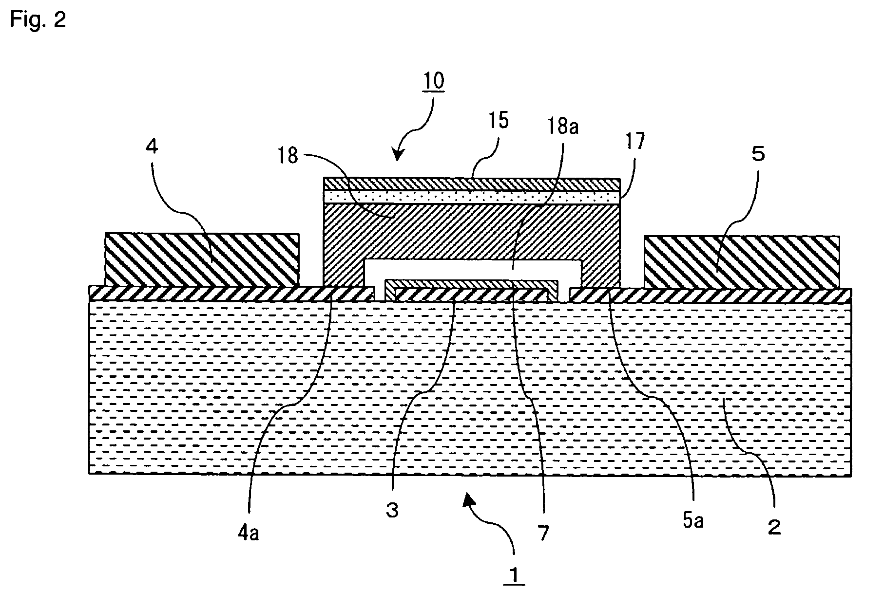
[0032]According to this constitution, since the wiring film thickness can be set at a desired film thickness without influencing contact force, variation in film thickness at the portion of contacts having film thickness smaller than that of the signal lines can be the minimum, the variation of the gap between the contacts can be reduced, the contact reliability between the contacts when they are closed is secured, and operations can be stabilized. In addition, since a skin depth required for flowing a current can be secured in the film thickness of the signal lines, the high frequency characteristics can be improved and the loss in transmission of the high frequency signal can be reduced.
[0035]According to this constitution, since there can be provided the apparatus in which responsibility is high, and the high frequency signal can be stably opened and closed for a long time with high reliability, high efficiency can be implemented because of low loss, a small size, and low power consumption in these apparatus.

Problems solved by technology

However, the following problems arises in the contact switch such as the electrostatic microrelay according to the prior art.
Consequently, the movable contact 209 cannot be sufficiently pushed toward the fixed contacts 206 so that contact reliability cannot be secured.
In this case also, there arises a problem that the contact reliability between the contacts cannot be obtained.

Method used


Image

  • Contact switch for high frequency application
  • Contact switch for high frequency application
  • Contact switch for high frequency application

Examples


first embodiment

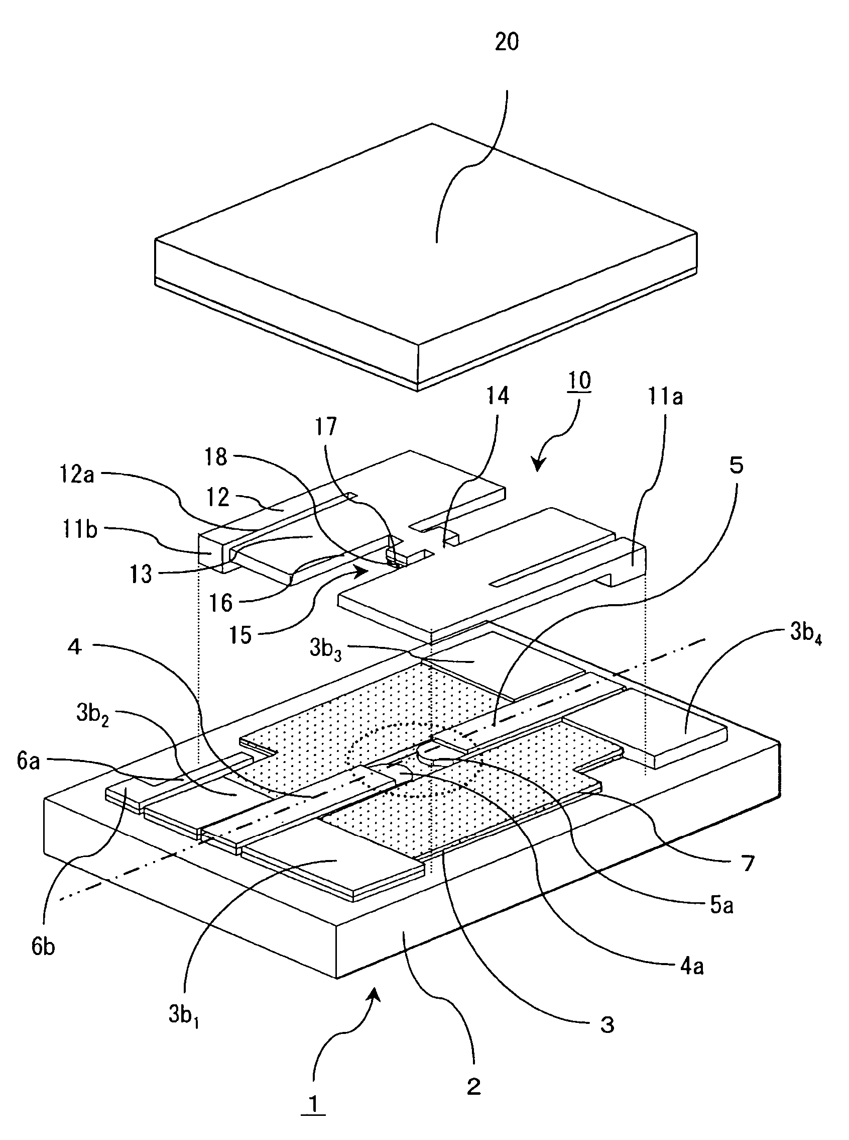
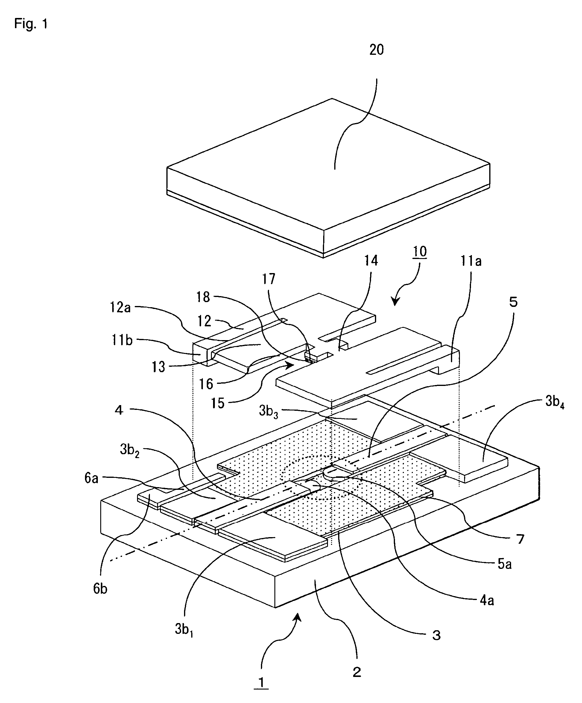
[0047]As shown in FIG. 1, the electrostatic microrelay has a constitution in which a movable substrate 10 is integrated on a surface of a fixed substrate 1 at a predetermined distance, and a cap 20 is provided so as to cover the movable substrate 10.

[0048]According to the fixed substrate 1, at least one fixed electrode 3 and two signal lines 4 and 5 are provided on an upper surface of a glass substrate 2.

[0049]The signal lines 4 and 5 are disposed on the same line (two-dot chain line in FIG. 1). The fixed electrode 3 is provided in a vicinity of the signal lines 4 and 5 at a predetermined distance so as to surround them and its surface is coated by an insulating film 7. Thus, the fixed electrode 3 is used also as a GND electrode (earth electrode) of a high frequency signal transmitting through the signal lines 4 and 5 to constitute Coplanar structure.

[0050]In other words, an electric flux line generated when the high frequency signal flows in the signal lines 4 and 5 is terminated ...

second embodiment

[0098]As shown in FIG. 5A, the microrelay is constituted such that a height of an upper face of a movable contact 18 and heights of the signal lines 4 and 5 may be the same when the movable contact 18 and the fixed contacts 4a and 5a are closed.

[0099]Still further, according to the second embodiment, as shown in FIG. 5B which is a top view of the signal lines 4 and 5 and the movable contact 18 shown in FIG. 5A, a width of the movable contact 18 in the direction perpendicular to the longitudinal direction of the signal lines 4 and 5 (referred to as a width hereinafter) may be almost the same as that of the signal lines 4 and 5. Thus, mismatching can be considerably controlled as compared to the prior art.

[0100]Since other constitutions of the microrelay according to the second embodiment are the same as in the first embodiment, a description thereof is omitted.

[0101]As described above, according to the second embodiment, since the same effect as in the first embodiment can be provid...


PUM


Abstract

A plurality of fixed contacts and signal lines are provided on a fixed substrate. A movable contact which is closed or opened with the fixed contacts is provided on a movable substrate opposed to the fixed substrate. A film thickness of the fixed contacts is made to be smaller than that of the signal lines so that the movable contact is set in a concave portion constituted by the fixed contacts when the fixed contacts, and the movable contact are closed and the signal lines are linearly connected.

Description

BACKGROUND OF THE INVENTION[0001]1. Field of the Invention[0002]The present invention relates to a contact switch and an apparatus comprising the contact switch.[0003]2. Description of the Background Art[0004]An electrostatic microrelay which is a form of the conventional contact switch is shown in FIG. 8. In FIG. 8, a perspective view of the electrostatic microrelay is shown in FIG. 8A and its sectional view taken along line b—b is shown in FIG. 8B.[0005]As shown in FIG. 8A, the electrostatic microrelay mainly consists of a fixed substrate 201 comprising a glass substrate or an insulator substrate, and a movable substrate 202 comprising a semiconductor such as silicon (Si).[0006]A fixed electrode 204 coated with an insulating film 203, and two signal lines 205 through which a high frequency signal passes are mainly provided on the one fixed substrate 201. The signal lines 205 are provided so as to be spaced at a predetermined distance and ends of the signal lines provide a couple o...

Claims


Application Information

Patent Timeline
IPC IPC(8): H01L21/40B81B3/00H01H59/00H01P1/12
CPCH01H59/0009H01P1/127H01H2059/0063H01H2001/0084H01H59/00
Inventor SEKI, TOMONORIUNO, YUTAKAMASUDA, TAKAHIRO
Owner ORMON CORP
Learn More