Dual coil probe for detecting geometric differences while stationary with respect to threaded apertures and fasteners or studs

a technology of geometric differences and probes, applied in the field of dual coil eddy current probes, can solve the problems of single coil probes and support electronics to compare parts to master parts, and the difficulty of separating non-conform parts from non-conform parts, so as to improve the detection accuracy and improve the detection accuracy. the effect of detecting electromagnetic threads and enhancing the detection accuracy

Inactive Publication Date: 2006-05-02
QUANTECH
View PDF22 Cites 10 Cited by
  • Summary
  • Abstract
  • Description
  • Claims
  • Application Information

AI Technical Summary

Benefits of technology

[0013]To further improve on the single coil probe approach, the present invention includes a dual coil element probe and support electronics. This provides enhanced electromagnetic thread detection. While the above-described, tuned probe, eddy current method has excellent performance for the vast majority of applications, in a few of these applications the conforming part population exhibits a greater spread of eddy current signatures. This is due to part-to-part variations in chemistry, microstructure / hardness, and possibly temperature and / or porosity. In these situations, while using a single coil, tuned probe, it can be more challenging to separate the non-conforming parts from the conforming part population, especially if relatively minor defects are to be found. By using a tuned, dual coil probe, differences in part-to-part chemistry and microstructure / hardness are very effectively eliminated, as are temperature variations. The present invention provides a greatly improved ability to ignore conforming part variations where function is not compromised, while at the same time, retaining an extremely effective ability at detecting thread depth, thread quality, and part porosity. The dual coil probe when used in a “static” mode of operation can be positioned at a specific depth where the stationary probe will not only sense the presence of threads, but the thread quality and the thread depth to within one thread or less, or the probe when used in a “dynamic” mode of operation can be combined with a linear variable differential transformer (LVDT) to sense the relative position of the dual coil probe with respect to the pierced surface of the part. This LVDT combined configuration for “dynamic” operation provides full aperture profiling capability to the user. All features, such as counter bore presence, counter bore depth, and thread quality throughout the aperture including thread depth can be detected. The present invention allows detection of these characteristics while eliminating concern about occasional variations in materials and temperatures that can sometimes limit such detection capabilities. An advantage of the dual coil probe according to the present invention is in determining the depth of threads in a part population that can vary with respect to temperature, chemistry, and microstructure / hardness, or where frequent re-calibration of the tuned, single coil probe is not likely to be performed. The dual coil probe can accomplish inspection of the part population to within less than one thread, consistently and without frequent re-calibration in either of the “static” and “dynamic” configurations.
[0016]It is desirable in the present invention to provide a substantial improvement in the ability to distinguish between parts that are threaded to the fully desired depth or length and those that are threaded to a shorter or longer depth or length then possible using a probe with a single coil as previously known. It is desirable in the present invention to compare the various amplitude and phase measurements of one coil to the same measurements from one or more other coils in or on the same part. It is desirable in the present invention to provide more than one coil in the part region being inspected simultaneously in order to make a comparison between the coils. It is desirable in the present invention to be able to distinguish between conforming and non-conforming parts within a population of parts that are threaded to the fully desired depth or length while exhibiting variations in temperature, chemistry, and / or microstructure or hardness. The ability of a single coil probe and support electronics to compare a population of parts to a master part on the basis of those parts which are similarly threaded and those with less than the desired thread or depth of threads is limited because the various amplitude and phase measurements of the coil can be affected by the previously mentioned non-geometrical variations, such as temperature, chemistry, microstructure, and / or hardness. The “static” or “dynamic” configuration of the dual coil probe, according to the present invention, effectively reduces or eliminates non-geometrical part-to-part variations and the comparison of measurements taken from one coil to those of the other coil or coils when both coils are used to inspect the same region of the same part.

Problems solved by technology

In these situations, while using a single coil, tuned probe, it can be more challenging to separate the non-conforming parts from the conforming part population, especially if relatively minor defects are to be found.
The ability of a single coil probe and support electronics to compare a population of parts to a master part on the basis of those parts which are similarly threaded and those with less than the desired thread or depth of threads is limited because the various amplitude and phase measurements of the coil can be affected by the previously mentioned non-geometrical variations, such as temperature, chemistry, microstructure, and / or hardness.

Method used


Image

  • Dual coil probe for detecting geometric differences while stationary with respect to threaded apertures and fasteners or studs
  • Dual coil probe for detecting geometric differences while stationary with respect to threaded apertures and fasteners or studs
  • Dual coil probe for detecting geometric differences while stationary with respect to threaded apertures and fasteners or studs

Examples


Embodiment Construction

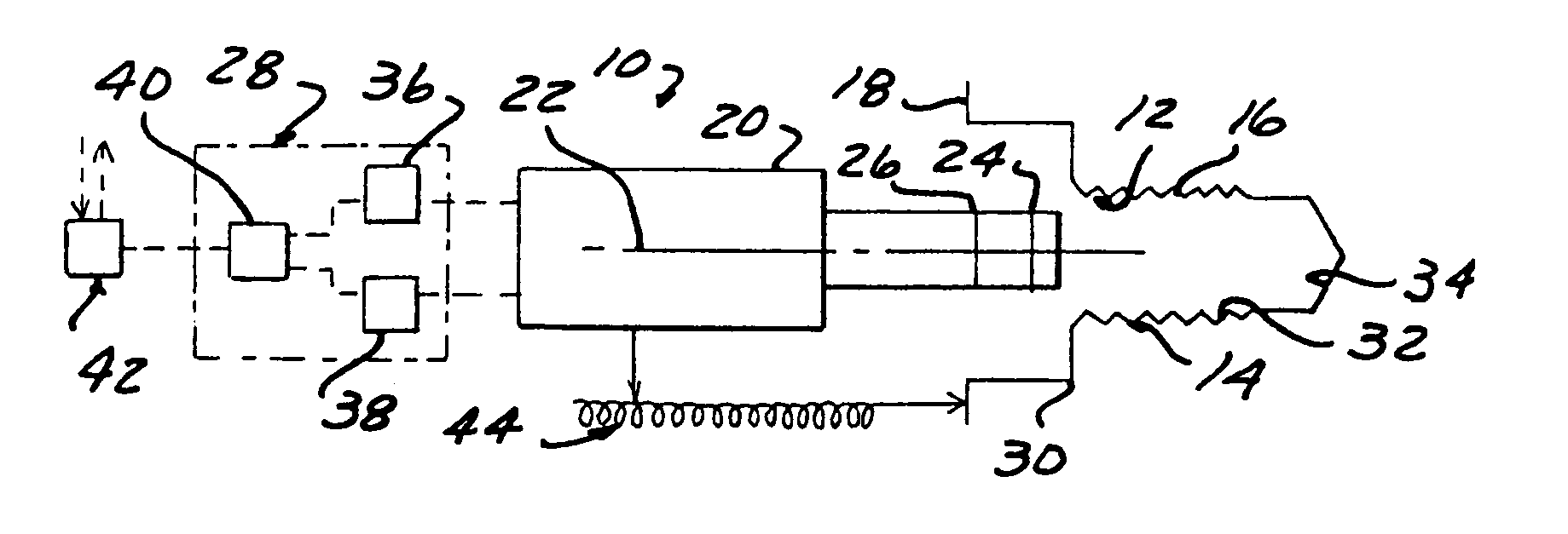
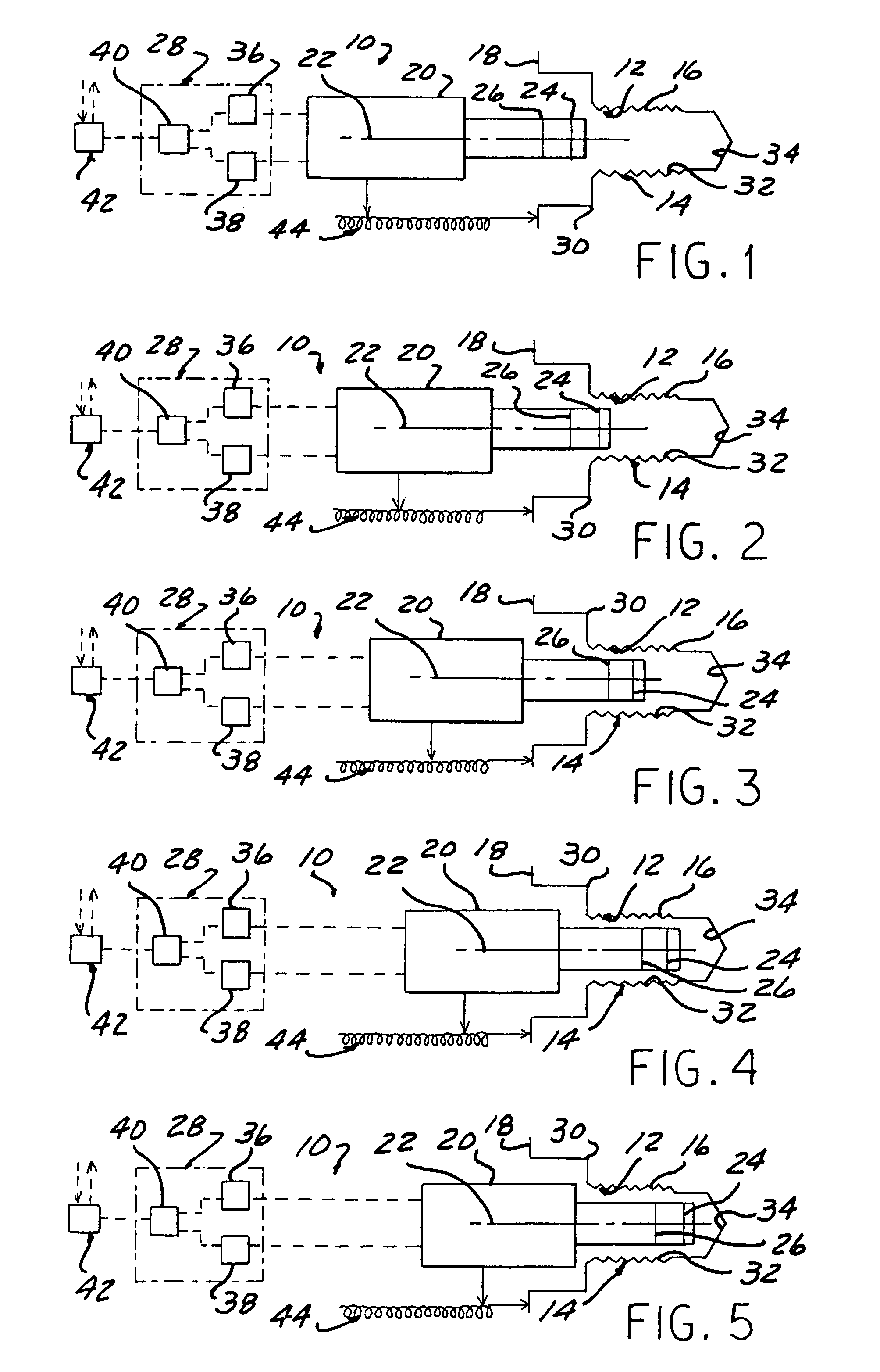
[0031]Referring now to FIGS. 1 through 5, an apparatus 10 is illustrated for inspecting contours 12 formed along a predetermined region 14 of a surface 16 on a workpiece 18 formed of an electrically conductive material using eddy current. A probe 20 is illustrated in FIG. 1 in a first position and has a longitudinal axis 22. The probe 20 when operating in a “static” configuration, or mode of operation, is moveable along a path of travel to a static testing position, such as the position illustrated in FIG. 5, with respect to the predetermined region 14 to be inspected on the workpiece 18. Preferably, the path of travel extends along the longitudinal axis 22 of the probe 20. At least two coils 24, 26 are spaced longitudinally from one another and supported by the probe 20 to be electrically excited with a predetermined frequency and amplitude while stationary at the static testing position. Means 28 can be provided for measuring the excitation voltage of each coil 24, 26 as eddy curr...


PUM

PropertyMeasurementUnit
voltageaaaaaaaaaa
voltageaaaaaaaaaa
electrically conductiveaaaaaaaaaa

Abstract

An apparatus and method is disclosed for inspecting contours formed along a predetermined region of a surface on a workpiece formed of an electrically conductive material using eddy current. A probe includes a longitudinal axis and is moveable along a path of travel to a static testing position stationary with respect to the predetermined region to be inspected on a workpiece. At least two coils are spaced longitudinally from one another and supported by the probe to be electrically excited with a predetermined frequency and amplitude while at the static testing position with the stationary probe. Sensors are provided for measuring the excitation voltage of each coil as eddy currents are induced in the electrically conductive material of the workpiece by the coils supported on the probe stationary at the static testing position with respect to the workpiece. A comparison is performed between the measured eddy current signals from the at least two coils, where a non-zero difference after the coils have encountered the predetermined region to be tested represents an end position of the predetermined region formed on the workpiece being tested.

Description

RELATED APPLICATIONS[0001]This application is a continuation-in-part of U.S. patent application Ser. No. 09 / 677,977 filed on Oct. 3, 2000, now U.S. Pat. No. 6,703,831, which was a continuation of U.S. Provisional Application Ser. No. 60 / 164,994 filed Nov. 12, 1999.FIELD OF THE INVENTION[0002]The present invention relates to a dual coil eddy current probe for detecting geometrical differences related to threaded apertures and fasteners or studs while stationary, and a method for detecting geometric differences using a stationary dual coil eddy current probe.BACKGROUND OF THE INVENTION[0003]Several hundred apertures are drilled and tapped in a typical automobile engine and the various components associated with the engine. Additional apertures are required when other drive train components are included, such as suspension components, various brackets and levers, frame and sheet metal parts and the like. The process of drilling apertures and tapping or roll head formed threads in engin...

Claims


Application Information

Patent Timeline
Patent Type & Authority Patents(United States)
IPC IPC(8): G01N27/82G01N27/90
CPCG01N27/904
Inventor KEELY, WILLIAM
Owner QUANTECH
Why Eureka
Try Eureka