Controller for wire electric discharge machine

a wire electric discharge machine and control board technology, applied in the direction of electric circuits, instruments, manufacturing tools, etc., can solve the problems of reducing the average machining voltage, affecting the gap voltage more than it is affected, and affecting the feed speed, so as to achieve stable machining and high surface accuracy

Active Publication Date: 2006-05-02
FANUC LTD
View PDF17 Cites 9 Cited by
  • Summary
  • Abstract
  • Description
  • Claims
  • Application Information

AI Technical Summary

Benefits of technology

[0020]The present invention provides a controller for a wire electric discharge machine which does not require adjustment of a gain ...

Problems solved by technology

Specifically, when the feed control is not performed appropriately (this often happens during machining under the conventional control), the discharge pulse density becomes unstable, so that produced sludge is unevenly distributed in the gap, so that the gap voltage is more affected than it is affected by the real change in the amount of machining per unit distance.
Once sludge is unevenly distributed and stays in the gap, discharge pulses are generated continuously due to the unevenly distributed sludge, which lowers the average machining voltage.
As a result, the feed speed decreases, which leads to further increase in the discharge pulse density and results in so-called too much removal.
As a result, irregularities such as undulation and lines are produced on the finished surface.
In this case, si...

Method used


Image

  • Controller for wire electric discharge machine
  • Controller for wire electric discharge machine
  • Controller for wire electric discharge machine

Examples


Embodiment Construction

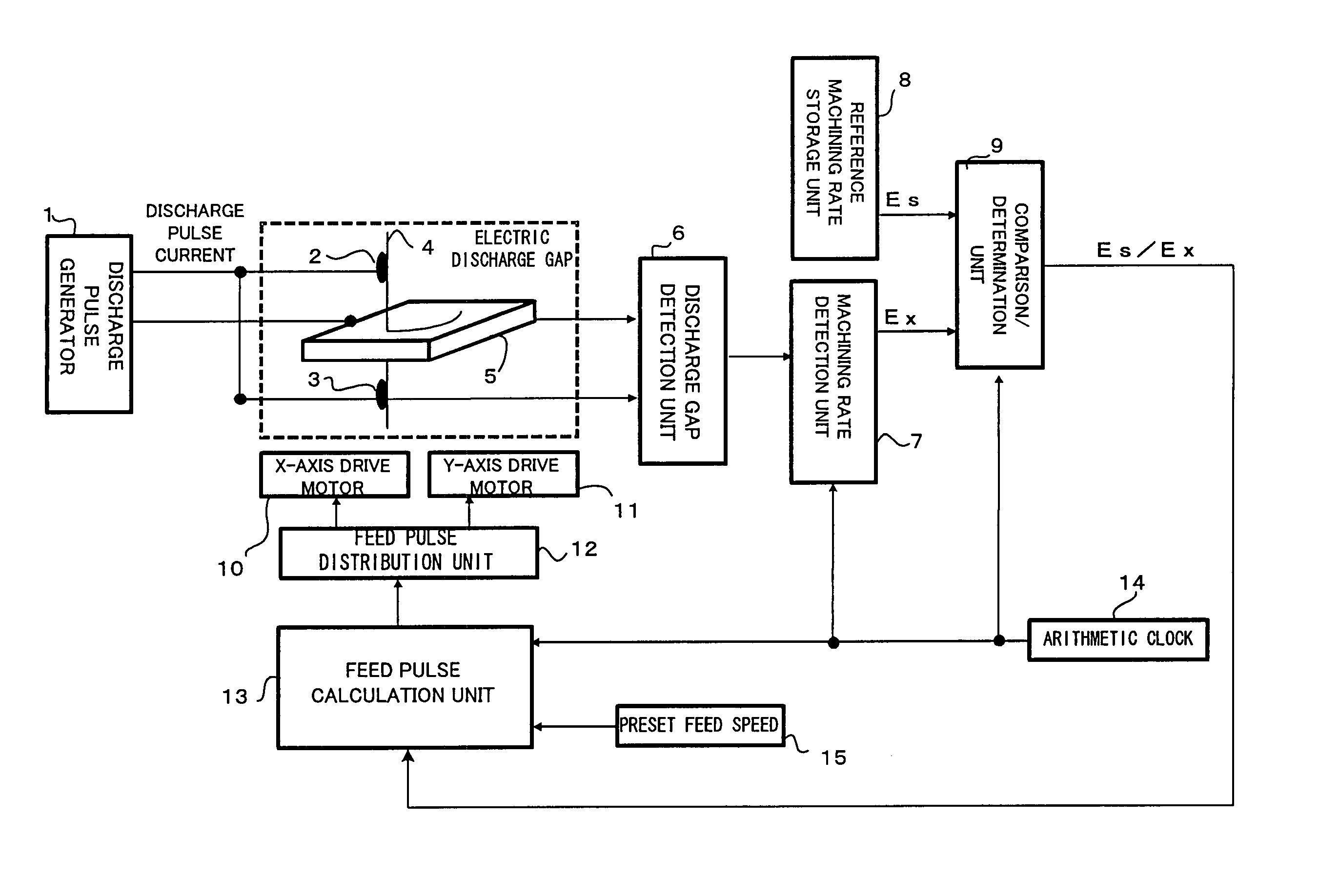
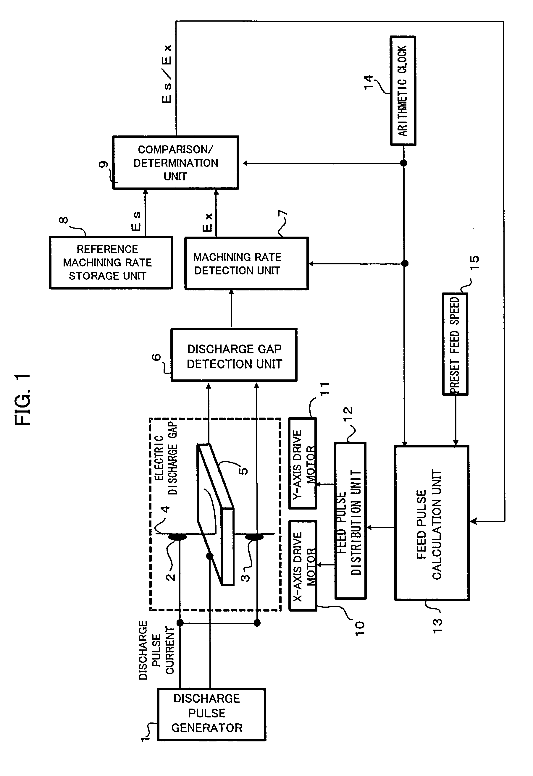
[0037]FIG. 1 is a block diagram showing relevant parts of a controller for a wire electric discharge machine according to the invention. A discharge pulse generator 1 is for applying a discharge pulse voltage to a gap between a wire electrode 4 and a workpiece 5 for electric discharge machining, and comprises a direct-current power source, a circuit including a switching element such as a transistor, a charge and discharge circuit for a capacitor, and others. Conductive brushes 2 and 3 are for making a current flow through the wire electrode, and connected to one of the two terminals of the discharge pulse generator 1. The workpiece 5 is connected to the other terminal of the discharge pulse generator 1. The discharge pulse generator 1 applies a pulse voltage between the wire electrode 4, which is traveling, and the workpiece 5. A table (not shown) on which the workpiece 5 is placed is driven by an X-axis drive motor control unit 10, a Y-axis drive motor control unit 11 and a pulse ...


PUM

PropertyMeasurementUnit
Ratioaaaaaaaaaa
Speedaaaaaaaaaa
Electric potential / voltageaaaaaaaaaa

Abstract

A controller for a wire electric discharge machine which can achieve stable machining with high surface accuracy without requiring adjustment of a gain or the like in wire-electrode feed control. A discharge gap detection unit detects a voltage between a wire electrode and a workpiece. An amount-of-machining-per-unit-distance change detection unit obtains an average machining voltage, and a voltage drop EX that is a difference between the obtained average machining voltage and a no-load voltage. A comparative determination unit obtains a ratio ES/EX between a reference voltage drop ES stored in a reference-amount-of-machining-per-unit-distance relative value storage unit and the drop voltage EX. A feed pulse arithmetic unit obtains a feed speed that makes the amount of machining per unit time constant, on the basis of the ratio ES/EX and a predetermined feed speed, and distributes feed pulses to motors to thereby move the wire electrode relatively to the workpiece. Since the amount of machining per unit time is kept constant, the surface accuracy in finishing is high and stable machining can be performed.

Description

BACKGROUND OF THE INVENTION[0001]1. Field of the Invention[0002]The invention relates to a controller for a wire electric discharge machine, specifically a controller for a wire electric discharge machine suitable for finishing in electric discharge machining.[0003]2. Description of the Related Art[0004]FIG. 10 is a block diagram showing parts relevant to feed control in a conventional wire electric discharge machine. A discharge pulse generator 1 is for applying a discharge pulse voltage to a gap between a wire electrode 4 and a workpiece 5 for electric discharge machining, and comprises a direct-current power source, a circuit including a switching element such as a transistor, a charge and discharge circuit for a capacitor, and others. Conductive brushes 2 and 3 are for making a current flow through the wire electrode, and connected to one of the two terminals of the discharge pulse generator 1. The workpiece 5 is connected to the other terminal of the discharge pulse generator 1...

Claims


Application Information

Patent Timeline
IPC IPC(8): G06F19/00B23H7/02B23H7/04B23H7/20
CPCB23H7/20B23H7/04
Inventor KURIHARA, MASAKIHIRAGA, KAORU
Owner FANUC LTD
Why Eureka
Try Eureka