
Vehicles and electromagnetic clutches for compressors for such vehicles

a technology of electromagnetic clutches and compressors, applied in the direction of positive displacement liquid engines, pumping, lighting and heating apparatus, etc., can solve the problems of excessive temperature increase and excessive temperature increase, and achieve the effect of preventing malfunctions, accurate detection, and avoiding wasteful power consumption

Active Publication Date: 2006-05-09
HONDA MOTOR CO LTD +1
View PDF35 Cites 2 Cited by
  • Summary
  • Abstract
  • Description
  • Claims
  • Application Information

AI Technical Summary

Benefits of technology

[0008]Accordingly, a need has arisen for vehicles and electromagnetic clutches for compressors for use in air conditioning systems for such vehicles, which overcome these and other deficiencies of the related art. A technical advantage of the present invention is that when an abnormal condition occurs in a compressor, or other portion of the air conditioning system the condition is recognized quickly and accurately by a control unit. Consequently, wasteful consumption of power and system malfunction may be avoided, overload to electromagnetic clutch and compressor also may be prevented, and the respective devices of the air conditioning system and the vehicle may be more completely protected.
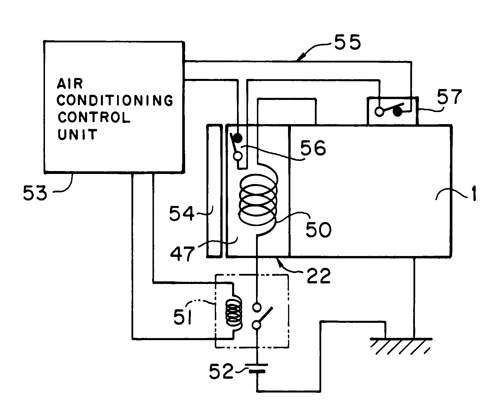
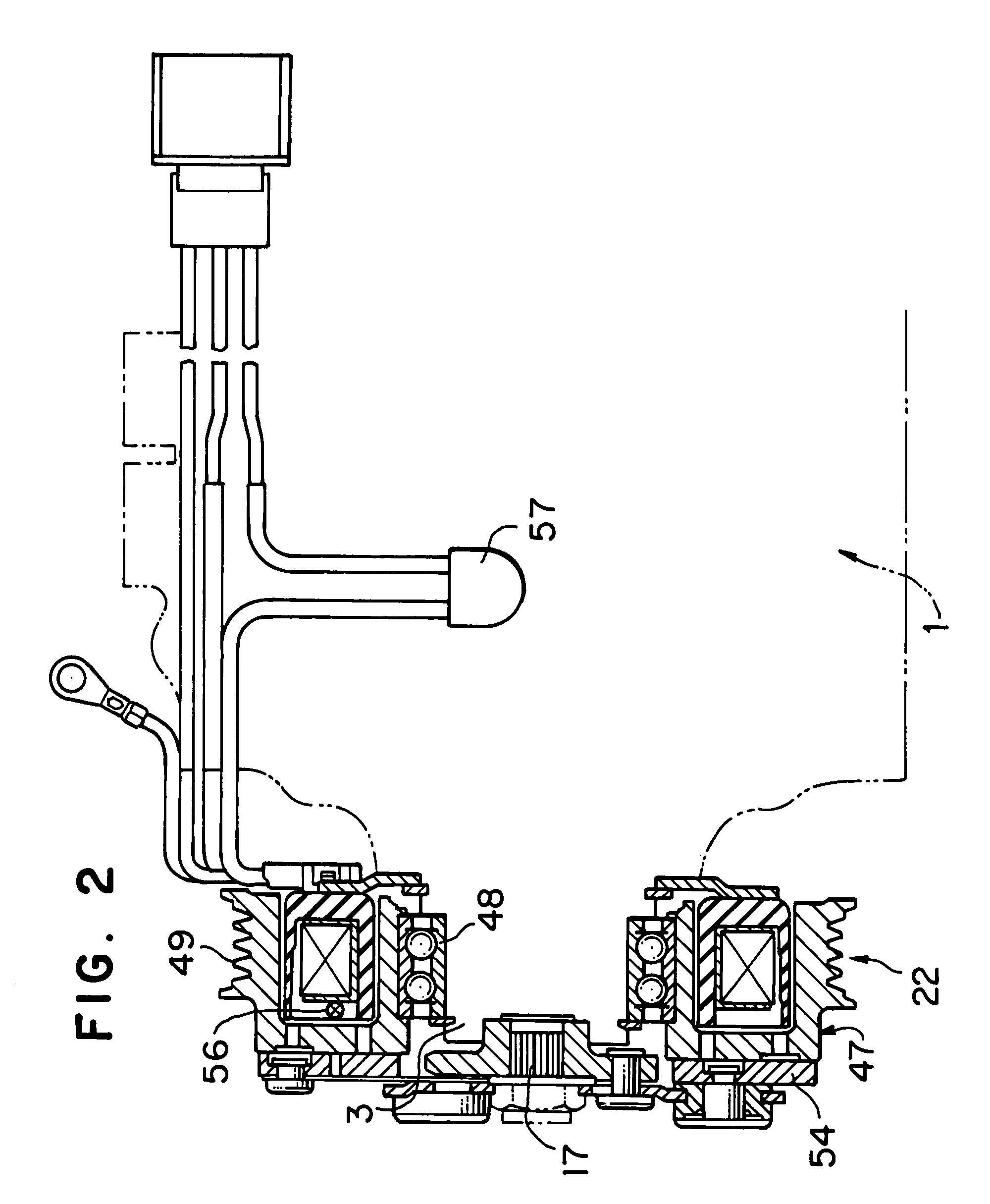
[0009]In an embodiment of the present invention, an electromagnetic clutch for a compressor comprises a rotor which receives a driving force from a drive source; an armature rotated integrally with a drive shaft of the compressor; an electromagnetic coil for bringing the rotor into contact with the armature by generating an electromagnetic attractive force due to the excitation of the coil to transmit the driving force to the drive shaft and for separating the rotor from the armature by terminating the excitation of the coil to interrupt the transmission of the driving force to the drive shaft; and a detection means for detecting an excessive increase in temperature. The detection means is provided via a first electric circuit separate from a second electric circuit of the electromagnetic coil. The detection means may detect an excessive increase in temperature, which may be ascribed to slippage between the rotor and the armature when the rotor and the armature are brought into contact with each other. Further, the detection means may detect an excessive increase in temperature ascribed to a temperature increase of compressed fluid (compressed refrigerant) discharged from the compressor.
[0010]The detection means comprises, for example, a temperature switch or a temperature fuse, or both. When the above-described compressor is used in an air conditioning system for a vehicle, the detection means preferably is connected to an air conditioning control unit for the air conditioning system. By connecting the detection means to the control unit, when a certain abnormal condition occurs in the compressor, the control unit immediately may detect this condition as an excessive increase in temperature; an appropriate response, such as terminating operation of the air conditioning system, may be enacted quickly, and, therefore, the electromagnetic clutch, the compressor, and heat exchangers in the air conditioning system may be protected properly.
[0011]In addition, the above-described compressor may be a hybrid compressor driven by two separate drive sources different, including an electric motor incorporated into the compressor. In the present invention, when an abnormal condition occurs in the electromagnetic clutch, or other portions of the air conditioning system and the transmission of the driving force from an external drive source (e.g., an engine) is interrupted, the condition is accurately detected by the detection means, and occurrence of malfunction, such as driving by or activation of the incorporated electric motor may be terminated promptly.
[0012]In another embodiment of the present invention, a vehicle comprises an electromagnetic clutch for a compressor, which includes a rotor which receives a driving force from a drive source; an armature rotated integrally with a drive shaft of the compressor; an electromagnetic coil for bringing the rotor into contact with the armature by an electromagnetic attractive force due to the excitation of the coil to transmit the driving force to the drive shaft and for separating the rotor from the armature by terminating the excitation of the coil to interrupt the transmission of the drive forcing to the drive shaft; and a detection means for detecting an excessive temperature elevation. The detection means is provided via a first electric circuit separate from a second electric circuit of the electromagnetic coil. The detection means may detect an excessive increase in temperature ascribed to slippage between the rotor and the armature when the rotor and the armature are brought into contact with each other. Further, the detection means may detect an excessive increase in temperature ascribed to a temperature increase of compressed fluid (compressed refrigerant) discharged from the compressor.
[0013]In addition, the detection means in this vehicle comprises a temperature switch or a temperature fuse, or both. When the compressor is used in an air conditioning system for the vehicle, the detection means preferably is connected to an air conditioning control unit for the air conditioning system. When the detection means detects an excessive increase in temperature, operation of the air conditioning system may be terminated. The compressor may be a hybrid compressor driven by two separate drive sources different from each other and including an electric motor incorporated into the compressor, and when the detection means detects an excessive increase in temperature, driving by or activation of the electric motor may be terminated.

Problems solved by technology

The detection means may detect an excessive increase in temperature, which may be ascribed to slippage between the rotor and the armature when the rotor and the armature are brought into contact with each other.
Further, the detection means may detect an excessive increase in temperature ascribed to a temperature increase of compressed fluid (compressed refrigerant) discharged from the compressor.

Method used


Image

  • Vehicles and electromagnetic clutches for compressors for such vehicles
  • Vehicles and electromagnetic clutches for compressors for such vehicles
  • Vehicles and electromagnetic clutches for compressors for such vehicles

Examples


Embodiment Construction

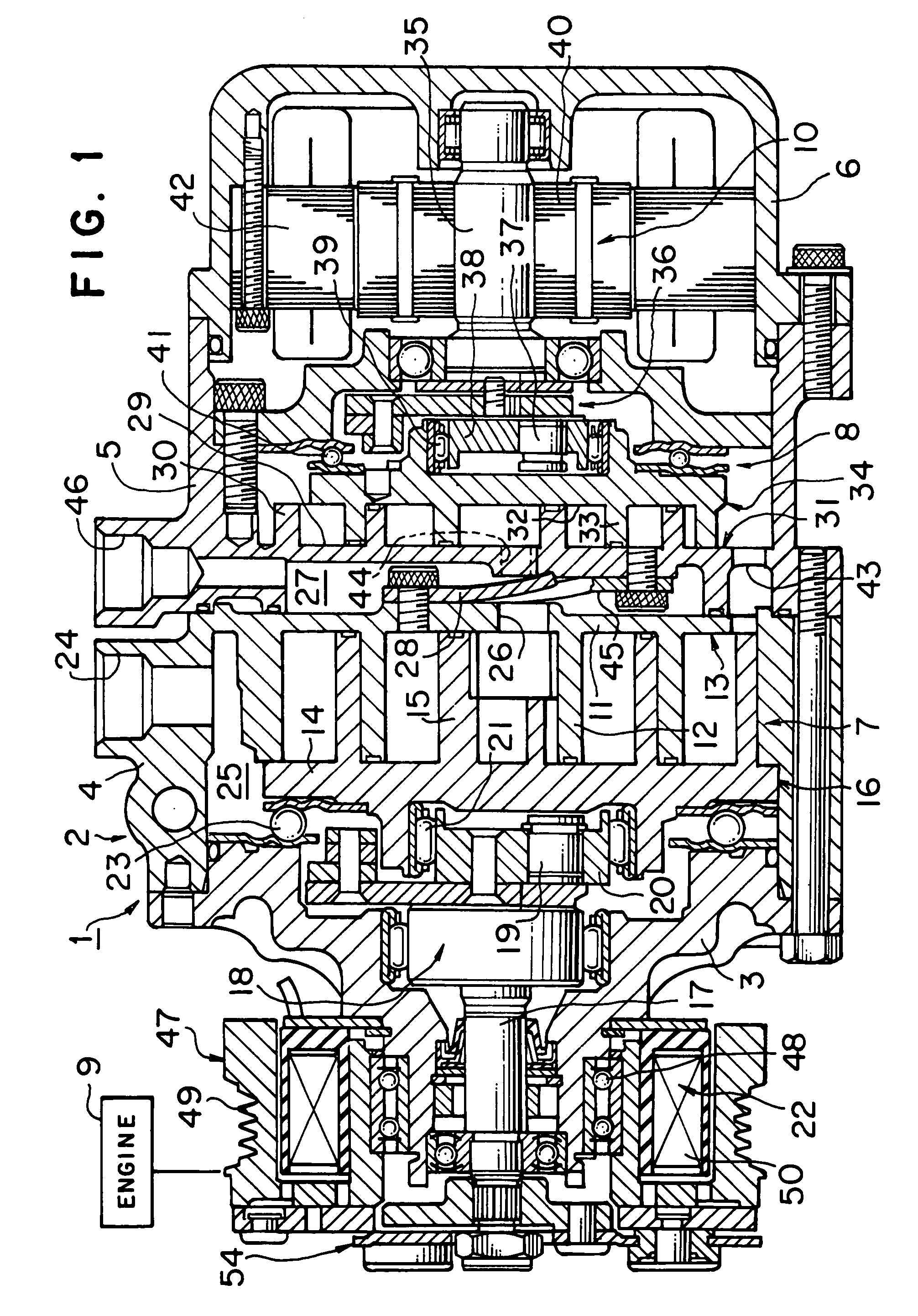
[0022]The present invention is described below with respect to a compressor used in a refrigerant circuit of an air conditioning system for vehicles. FIG. 1 depicts a compressor using an electromagnetic clutch according to a first embodiment of the present invention. In FIG. 1, compressor 1 is depicted as a hybrid compressor driven by two separate drive sources, different from each other and including an electric motor incorporated into compressor 1. Hybrid compressor 1 has housing 2, and housing 2 is formed from front housing 3, first housing 4, second housing 5, and rear housing 6 connected in this order from the left side of FIG. 1. First compression mechanism 7 and second compression mechanism 8 are provided within housing 2.

[0023]First compression mechanism 7 is driven by engine 9 provided as a vehicle drive source. Second compression mechanism 8 is driven by electric motor 10 incorporated into rear housing 6. Driving by engine 9 and driving by electric motor 10 may be carried ...


PUM


Abstract

An electromagnetic clutch for a compressor includes a rotor, an armature, an electromagnetic coil for bringing the rotor into contact with the armature and for separating the rotor from the armature, and a temperature detection device, such as a temperature fuse or a temperature switch, or both, for detecting an excessive increase in temperature ascribed to slippage between the rotor and the armature or a temperature increase of refrigerant discharged from the compressor. An electric circuit of the temperature detection device is separated from the electric circuit of the electromagnetic coil. An abnormal condition may be accurately detected by the separate circuit structure, and a proper response to the abnormal condition may be taken quickly.

Description

BACKGROUND OF THE INVENTION[0001]1. Field of the Invention[0002]The present invention relates generally to vehicles and electromagnetic clutches for compressors for use in air conditioning systems such vehicles. In particular, the present invention relates to vehicles and electromagnetic clutches for compressors, in which an excessive temperature elevation in an electromagnetic clutch may be accurately detected, thereby ensuring proper operation of the electromagnetic clutch and a compressor.[0003]2. Description of Related Art[0004]Generally, in the drive control of a compressor used in a refrigeration cycle of an air conditioning system for vehicles, the transmission and interruption of a drive force from a drive source, e.g., an engine, to the compressor are controlled by an electromagnetic clutch. FIG. 5 depicts a schematic diagram of a known electromagnetic clutch for a compressor. In FIG. 5, electromagnetic clutch 101 is mounted on compressor 100 for controlling the transmissio...

Claims


Application Information

Patent Timeline
IPC IPC(8): B60H1/32F25B1/00F25B49/00F04B49/10F04B35/00F16D27/112F16D27/14
CPCB60H1/3225F16D27/112F16D2027/002
Inventor HIGASHIYAMA, AKIYOSHIADACHI, HIROMITSUWATANABE, HIDEKIWAKOU, SHINICHIROU
Owner HONDA MOTOR CO LTD
Learn More