
Low harmonic diode clamped converter/inverter

Active Publication Date: 2006-05-09
BAKER HUGHES INC
View PDF6 Cites 38 Cited by
  • Summary
  • Abstract
  • Description
  • Claims
  • Application Information

AI Technical Summary

Benefits of technology

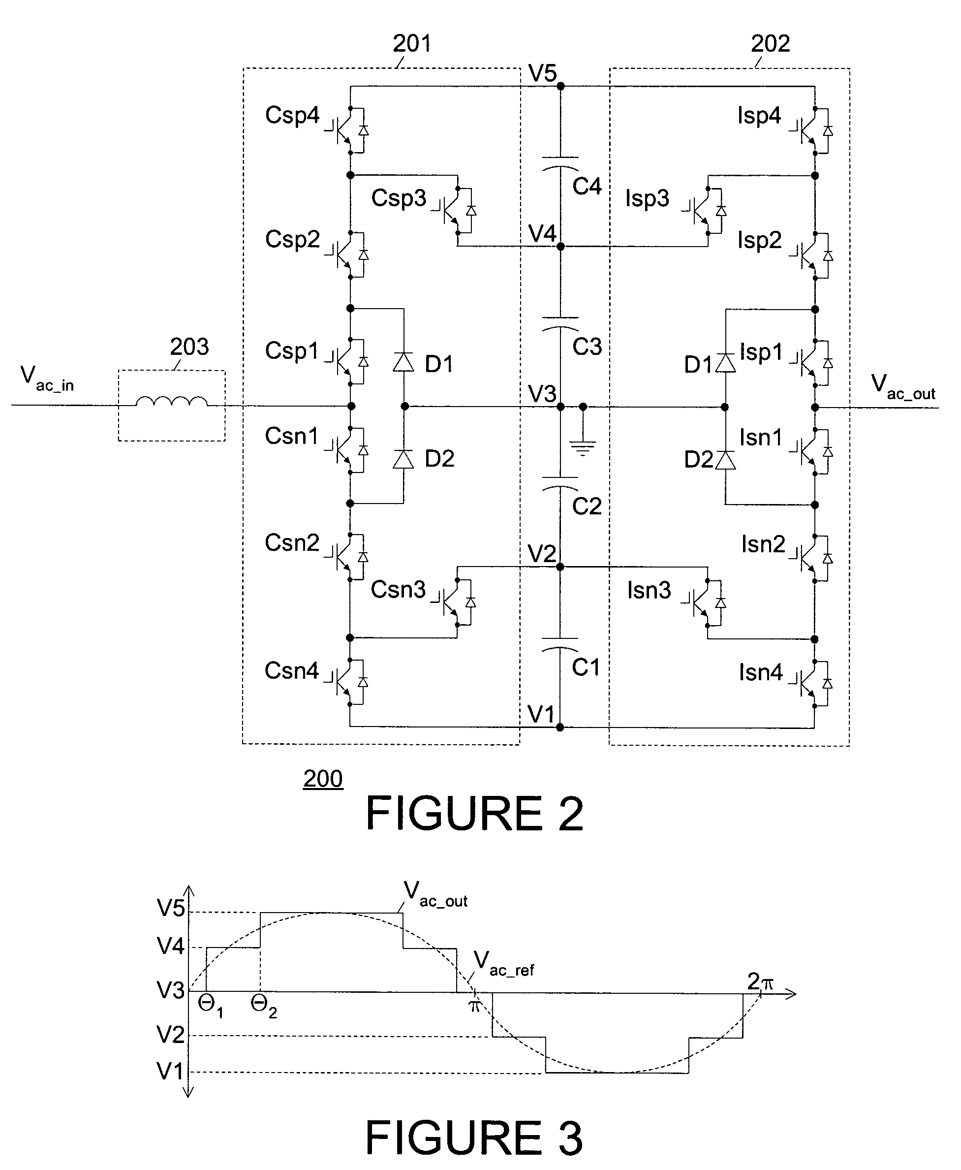
[0005]To address the above-discussed deficiencies of the prior art, it is a primary object of the present invention to provide, for use in a borehole production system, first and second networks of switching devices, each of which are an insulated gate bipolar transistor with an intrinsic reverse-biased clamping diode, that are controlled to selectively connect a sinusoidal input voltage and an output to different nodes within a series of capacitors during different portions of input and output voltag

Problems solved by technology

However, pulse width modulation often produces ringing or resonance in the transmitted power, resulting in extremely high peak voltages that may, over time, degrade or destroy the power cable insulation, cause vibration damage to the pump, or cause other undesirable side effects.
Sine wave filters used to smooth the pulse width modulated output are expensive and complex.

Method used


Image

  • Low harmonic diode clamped converter/inverter
  • Low harmonic diode clamped converter/inverter
  • Low harmonic diode clamped converter/inverter

Examples


Embodiment Construction

[0014]FIGS. 1 through 5, discussed below, and the various embodiments used to describe the principles of the present invention in this patent document are by way of illustration only and should not be construed in any way to limit the scope of the invention. Those skilled in the art will understand that the principles of the present invention may be implemented in any suitably arranged device.

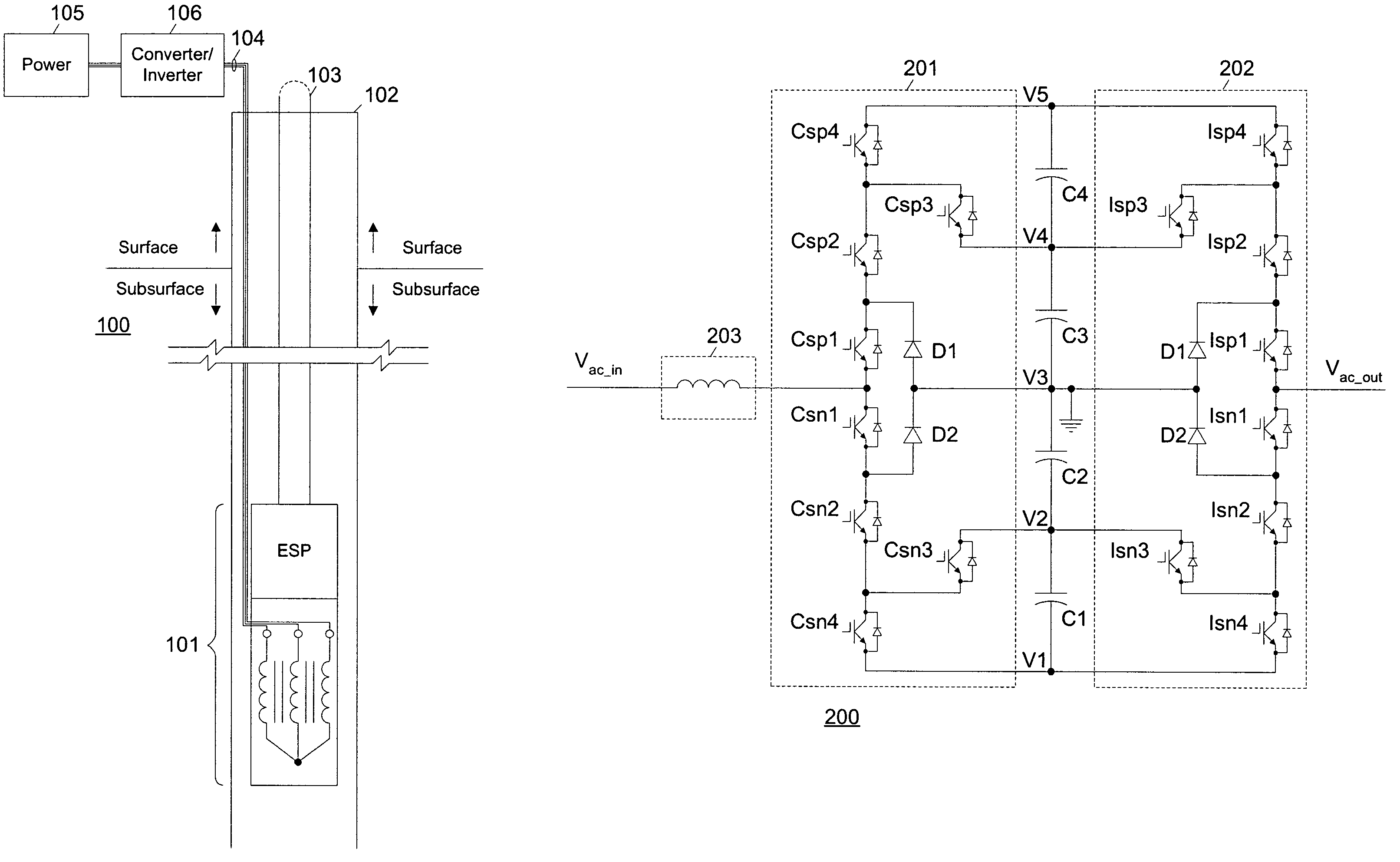
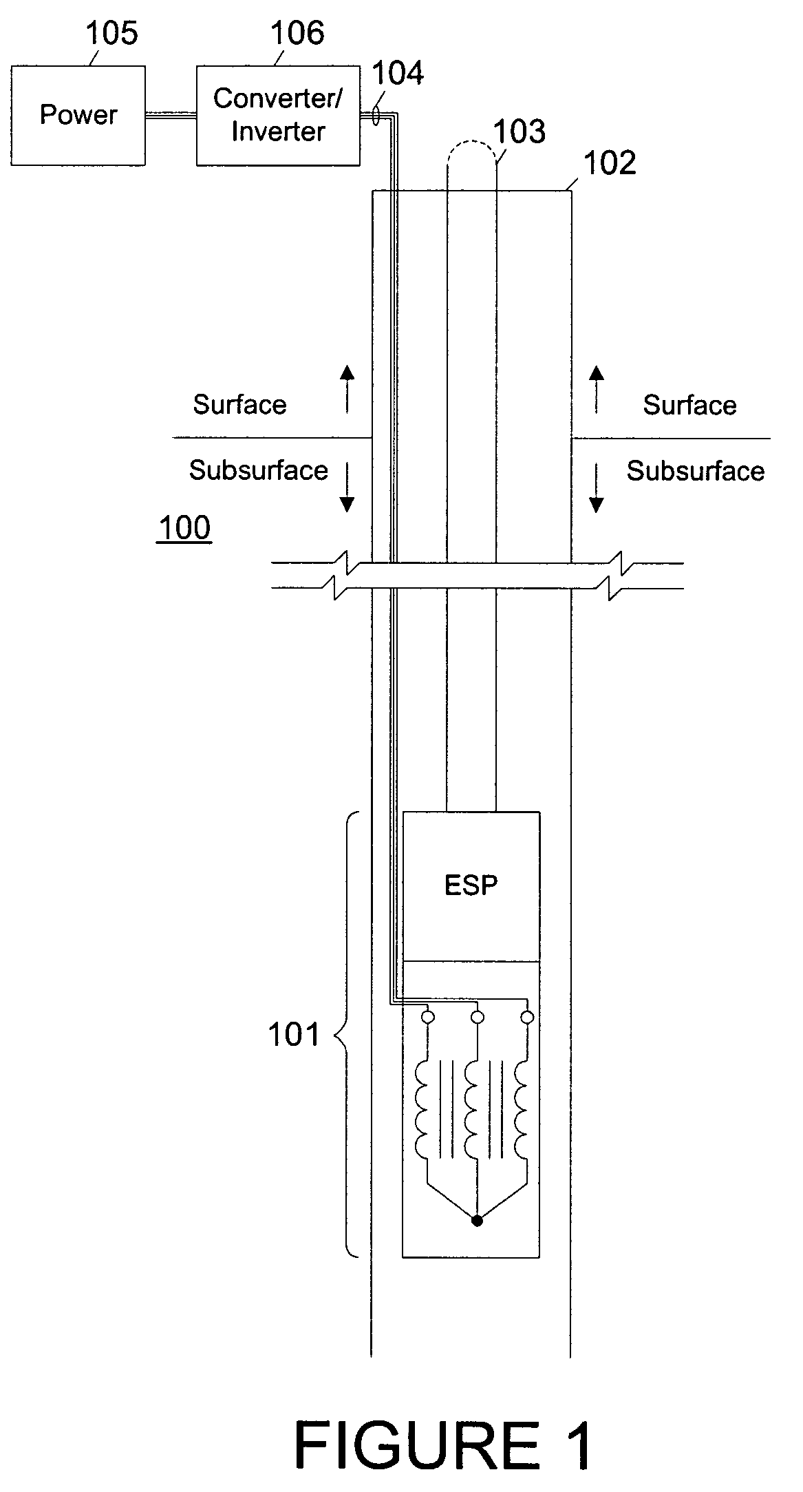
[0015]FIG. 1 depicts a borehole production system including a converter / inverter system according to one embodiment of the present invention. Borehole production system 100 includes an electrical submersible pump and motor assembly 101 lowered into a borehole 102 using a production tubing string 103. A three-phase power cable 104 carries three-phase power into the borehole 102 to the motor within assembly 101 from a surface location.

[0016]At the surface, a three-phase power source 105, such as a generator or a connection to a local power grid, is coupled to power cable 104 by a converter / invert...


PUM


Abstract

First and second networks of switching devices, each of which are an insulated gate bipolar transistor with an intrinsic reverse-biased clamping diode, are controlled to selectively connect a sinusoidal input voltage and an output to different nodes within a series of capacitors during different portions of input and output voltage cycles to produce a stepped sinusoidal output voltage. The topology requires a low part count, produces relatively low harmonics without filtering when powering artificial lift equipment within a borehole, and scales up to medium voltages without a step-up transformer. During variable speed operation of the lift equipment, optimized switching angles for controlling the switching devices during the voltage cycles may be selected based on modulation producing the desired speed and phase measurements.

Description

TECHNICAL FIELD OF THE INVENTION[0001]The present invention is directed, in general, to borehole production power systems and, more specifically, to low harmonic borehole production power systems allowing variable speed operation of artificial lift equipment.BACKGROUND OF THE INVENTION[0002]In borehole production systems that employ artificial lift equipment such as electrical submersible pumps (ESPs), variable speed operation is typically achieved by either quasi-sine wave “six-step” modulation, which produces fifth and seventh harmonics of significant magnitude, or pulse width modulated (PWM) drives, in which sinusoidal load currents are produced by varying the “width” or duration of high frequency square waves in order to vary the operating speed of a motor coupled to the drive via a power cable and, optionally, a step-up transformer.[0003]However, pulse width modulation often produces ringing or resonance in the transmitted power, resulting in extremely high peak voltages that m...

Claims


Application Information

Patent Timeline
IPC IPC(8): E21B43/00H02M5/458H02M7/48H02M7/483H02P27/14
CPCH02M5/4585H02P27/14H02M7/483H02M7/487H02M7/4833
Inventor LEUTHEN, JOHN MICHAELPENG, FANG ZHENG
Owner BAKER HUGHES INC
Learn More