
Compressor provided with torque limiter

Active Publication Date: 2006-05-09
DENSO CORP +1
View PDF19 Cites 7 Cited by
  • Summary
  • Abstract
  • Description
  • Claims
  • Application Information

AI Technical Summary

Benefits of technology

[0011]Therefore, when the compressor is in normal operation and the torque load acting upon the compressor is within the range of normal value, the one-way clutch is in an engaged state so as to transmit the rotational power efficiently from the rotational power source to the compressor, but when the torque load acting upon the rotation shaft increases unusually due to some cause such as locking of the compressor or the like, the one-way clutch section becomes disengaged so that the transmission of the rotational power from the rotational power source to the compressor is shut off, and the shut-off state is maintained. Thus, the one-way clutch section acts as a torque limiter so that no excessive torque load acts on the rotational power source, and no torque shock occurs and no damage is produced in the rotational power source.
[0013]When the one-way clutch section is constructed as a roller type one-way clutch, in addition to forming a first pocket section usually provided in the circumferential direction on one side of the wedge surface on the outer ring or the inner ring engaged with the roller of the one-way clutch section, a second pocket section can be formed on the other side of the wedge surface such that, when the torque load increases unusually and exceeds a predetermined value, the roller may fall into the second pocket to be disengaged from the wedge surface so as to prevent the excessive torque load from giving an adverse effect upon the rotational power source.
[0015]When a shock absorbing damper formed of an elastic material is provided in the power transmission path, the shock due to the torque variation can be reduced, and ingress of foreign substance such as dust, water, oil or the like, into the power transmission mechanism, can be avoided by suitable design of the structure of the shock absorbing damper.
[0018]When a bearing section is provided together with the one-way clutch section used in the power transmission mechanism of the compressor of the present invention, the concentricity of the outer ring and the inner ring of the one-way clutch section can be maintained easily.
[0019]The one-way clutch section used in the power transmission mechanism of the compressor of the present invention may be provided outside the housing of the compressor, or may be incorporated inside the housing of the compressor. In the latter case, the lubrication of the one-way clutch section can be carried out jointly by using the lubricant oil circulating in the compressor. Thus, the lubricating system can be simplified and the wear and overheating of the one-way clutch section can be reliably prevented.

Problems solved by technology

When a compressor is constructed in this manner, by using a one-way clutch instead of an electromagnetic clutch, such that the rotation shaft of the compressor is always kept rotating while the internal combustion engine is operated, the torque load acting upon the rotation shaft of the compressor may become excessively large in the event of failure or locking of the compressor and, as a result, the belt between a crank shaft pulley of the internal combustion engine and a pulley on the compressor side may be broken, or the internal combustion engine may come to a stop and the vehicle cannot keep running on, or a torque shock may be produced that gives uncomfortable sensation to the passengers in the vehicle.
However, this may give rise to another problem such as increase of the number of parts, increase of size due to required additional space for providing such a member around the pulley or the like, or complicated shape being required for parts such as pulley.
Moreover, in the prior art as described above, the function of a torque limiter is realized by breakage of a member and, as the timing of the occurrence of breakage of the member fluctuates depending upon various factors such as the surface characteristics of the member, metallography of the material, temperature, and age deterioration, there arises another problem that the member may break during normal operation or the member may not break even if the predetermined torque is exceeded.

Method used


Image

  • Compressor provided with torque limiter
  • Compressor provided with torque limiter
  • Compressor provided with torque limiter

Examples


first embodiment

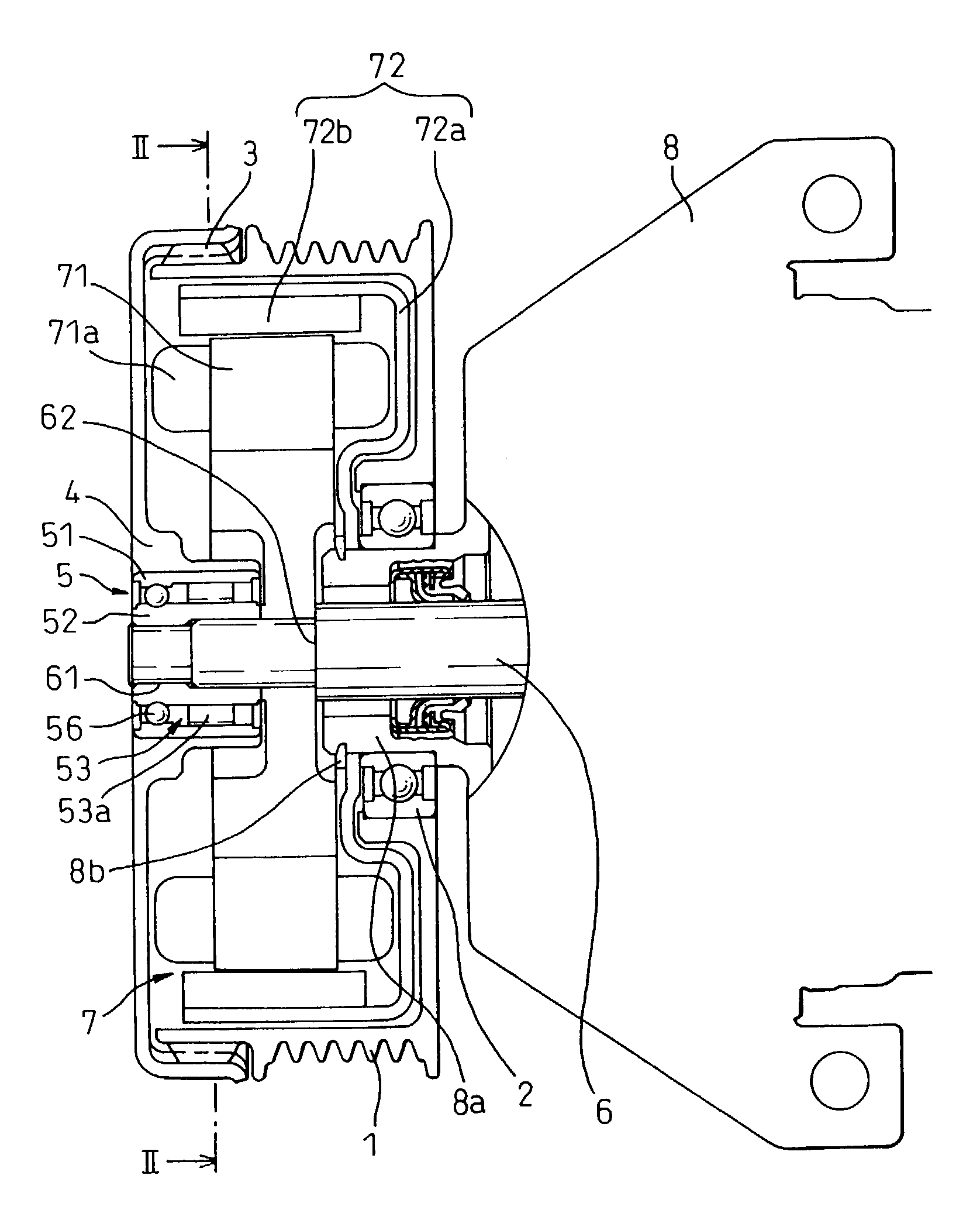
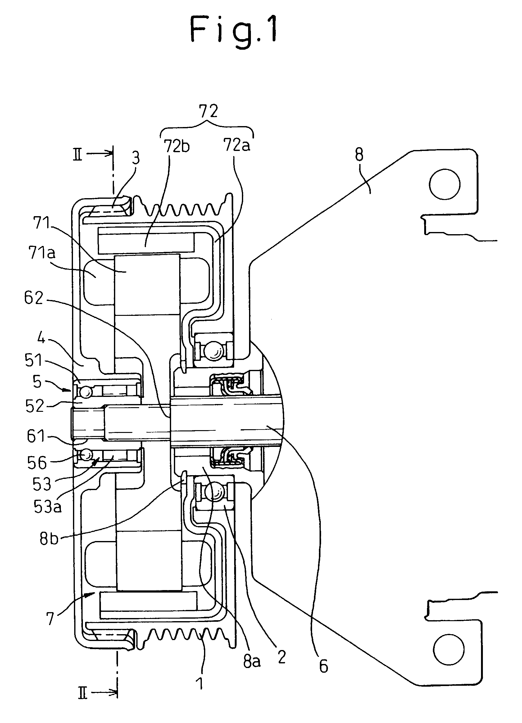
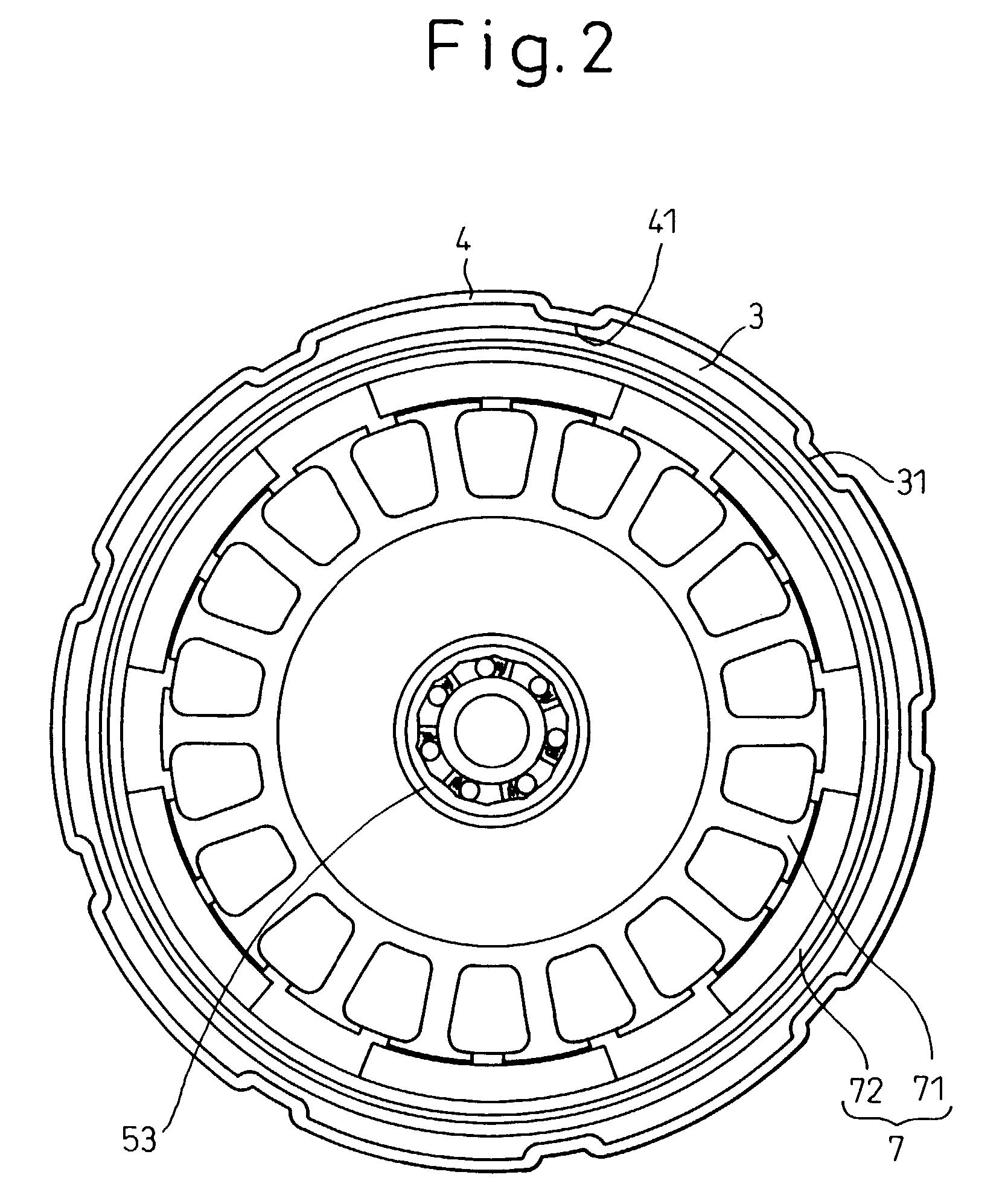
[0029]A compressor provided with a torque limiter according to the present invention will be described in detail with reference to FIGS. 1 to 4 showing a first embodiment thereof. The compressor itself is a swash-plate type, a scroll type, a vane type or other displacement compressor, and is constructed such that it can achieve an operating state with a zero displacement volume. However, the feature of the present invention does not consist of the construction of the compressor but of the power transmission mechanism provided in the compressor.

[0030]The power transmission mechanism belongs to the so-called hybrid drive type mechanism. When the compressor is used as a refrigerant compressor in an air-conditioning system mounted on a vehicle, the power transmission mechanism is used to rotationally drive the compressor selectively using either an internal combustion engine (not shown) which is the main power source for driving the vehicle or an electric motor incorporated in the power...

second embodiment

[0052]Thus, in accordance with the compressor in the second embodiment, when an internal combustion engine as the main power source is being operated and the compressor 8 is being rotationally driven by the internal combustion engine in the direction R, the sprag type one-way clutch section 54 is in the normal engagement state as shown in FIG. 6 so as to transmit the torque, and when the internal combustion engine has come to a stop and the compressor 8 is rotationally driven by an electric motor 7 in the direction R, the sprag 54a is slightly tilted so as to bring the one-way clutch section 54 into disengaged state so that, even if the inner ring 52 and the rotation shaft 6 are rotated by the electric motor 7, the outer ring 55, together with the pulley 1 and the hub 4, can remain at rest.

[0053]In the event where the compressor 8 happens to be locked, the sprag 54a of the sprag type one-way clutch section 54 is reversed by an unusually increased torque load to the state of roll-ove...

fourth embodiment

[0068]In the compressor 8 of the fourth embodiment, a one-way clutch unit 5 is provided between the rotation shaft 6 and the drive plate 13, and when the rotation shaft 6 is rotationally driven via the pulley 1 or the like by a power source such as an internal combustion engine in the drive direction of the compressor 8, the one-way clutch section 53 is in engaged state to transmit the power to the drive plate 13 and to rotate the swash-plate 15. Thus, when the pulley 1 is rotating, the drive plate 13 and the swash-plate 15 are always rotating. If the air-conditioning system need not be operated, the control pressure of the swash-plate chamber 26 is maximized to bring the tilt angle of the swash-plate 15 to zero and the reciprocating motion of the pistons 24 is stopped. Therefore, the compressor 8 is in an idling state and consumes little power in this case, so that an electromagnetic clutch or the like needs not be provided between the pulley 1 and the rotation shaft 6 to shut off ...


PUM


Abstract

A compressor provided with a torque limiter constructed such that, in view of possible occurrence of accidental locking of the compressor, in the case where a one-way clutch is used in place of an electromagnetic clutch in order to permit a refrigerant compressor for a vehicle air-conditioning system to be driven by an electric motor instead of an internal combustion engine, when an excessive torque is to be transmitted by the one-way clutch, rollers ride over wedge surfaces and fall into pocket sections, or sprags are reversed to roll-over.

Description

BACKGROUND OF THE INVENTION[0001]1. Field of the Invention[0002]The present invention relates to a compressor, and more particularly to a compressor that is provided with a torque limiter and is suitable for use as a refrigerant compressor in an air-conditioning system mounted on a vehicle.[0003]2. Description of the Related Art[0004]A refrigerant compressor for an air-conditioning system mounted on a vehicle such as an automobile is rotationally driven, while the vehicle is running, by a vehicle-mounted internal combustion engine which is the main power source for driving the vehicle, but if it is required to operate the air-conditioning system when the internal combustion engine has come to a stop by idling-stop control or the like, the compressor is rotationally driven by an electric motor operated by a battery mounted on the vehicle as an auxiliary power source. Such a compressor that is driven selectively by one of plural power sources is called as a composite-drive type compre...

Claims


Application Information

Patent Timeline
IPC IPC(8): F04B49/00F04B49/10F04B35/00F16D41/066F16D41/07
CPCF16D41/073F16D41/066
Inventor UEDA, MOTOHIKOTABUCHI, YASUOMERA, MINORUADANIYA, TAKUARAI, TOMOHARU
Owner DENSO CORP
Learn More