
System and method for accessing the coronary sinus

a system and catheter technology, applied in the field of intravascular catheters, can solve the problems of insufficient blood flow to the patient's kidneys, lack of stamina, shortness of breath, etc., and achieve the effect of facilitating the location of the patient's coronary sinus ostium

Inactive Publication Date: 2006-05-09
CARDIAC PACEMAKERS INC
View PDF12 Cites 32 Cited by
  • Summary
  • Abstract
  • Description
  • Claims
  • Application Information

AI Technical Summary

Benefits of technology

[0014]The invention is generally directed to an accessing system for a patient's intracorporeal opening of a body cavity such as the coronary sinus ostium and particularly for advancing therapeutic and diagnostic devices into the patients coronary sinus and related cardiac veins. The improved accessing system facilitates location of the patient's coronary sinus ostium, the advancement of therapeutic or diagnostic devices into the coronary sinus and associated coronary veins and maintaining the position of such devices during the procedure, particularly with patients having deformed hearts such as those suffering from CHF.
[0018]In this manner, the distal end of the tubular support member directs the guide member, as it extends, toward the RA wall. One or more stabilizing members are associated with the tubular support member to stabilize the position of the tubular support member's distal end relative to the patient's right atrium and, therefore, relative to the patient's coronary sinus ostium. This stabilization provides the support necessary for inserting the guide member and, subsequently, other devices via the guide member into the coronary sinus. Also the stabilizing member(s) create a stable repeatable path about which the tubular support member may be rotated and / or translated longitudinally along within the patient's right atrium. By rotating and longitudinally moving the tubular support member and longitudinally moving the guide member within it, the contact locations on the atrium wall by the distal end of the guide member can sweep over a wide region. A pattern of sequential sweeps or contact locations of the distal end of the guide member against the atrial wall ensures rapid accessing of the ostium of the patient's coronary sinus. Rotation and / or longitudinal movement of the tubular support member will point the shaped distal end of the tubular support member so that the distal end of the guide member will make a series of contacts with or sweeps against the atrial wall in a series of vertical, horizontal or other patterned contact locations. As physicians gain experience with this device, they will quickly settle on their preferred search pattern / technique to most quickly locate and gain access to the coronary sinus.
[0021]In this embodiment, it is also preferred that a clamp device be used to fix the proximal end of the guidewire-like elongated device relative to the patient or the proximal end of the introducer sheath. This ensures that the non-traumatic tip of the guidewire-like elongated device remains positioned in the apex of the right ventricle and is not subject to much rotation or translation during manipulations of the tubular support and guide members. This provides further stabilization. If the guidewire-like elongated device were designed such that its non-traumatic tip can rotate or the rotation of the non-traumatic tip will not damage the RV or the guidewire-like elongate device, then the clamp device may allow rotation of the guidewire-like elongated device. The clamp device may also serve as a stable platform for the manipulation (rotation and translation) of the tubular support member about the proximal end of the guidewire-like elongated device.
[0022]In another embodiment of the invention, the stabilizing member is a guiding catheter having a shaped distal end which is configured to hold the tubular support member in a desired orientation within the patient's right atrium while trying to locate the CS ostium and delivering the guide member into the patient's CS and advancing the guide member into related blood vessels which drain into the CS. The shaped distal end of the guide catheter should be relatively stiff in order to hold its position in the RA and thus provide a stabilized platform from which to manipulate the tubular support member.
[0023]In this embodiment, it is preferred that the distal end of the tubular support member incorporate a spring-like wire or other material construction to provide an elastically deformable, but stiffened section. This section would be proximal of the tubular support member's shaped end and extend proximally into the distal end of the guiding catheter during use. This section would increase the ability for the guiding catheter to support the tubular support member during use and ensure the path repeatability of tubular support member as it is advanced, retracted or rotated within the guiding catheter. As before, it is also preferred that a clamp device be provided that fixes the position of the proximal end of the guiding catheter relative to the patient or the proximal end of the introducer sheath to provide additional stabilization.

Problems solved by technology

The condition results in the patient having shortness of breath, weakness and a lack of stamina, fatigue, exercise intolerance and fluid retention which results from an inadequate flow of blood to the patient's kidneys.
The harder the heart works to pump more blood, the more enlarged it becomes.
Often, by the time symptoms are noticed by the patient, the enlargement is pronounced and the heart is unable to provide enough cardiac output to support normal lifestyle activity.
Conversely, drug treatments that lower cardiac output tend to slow the progression of the disease.
However, this can severely limit the patients lifestyle, leaving many patients effectively immobile or worse.
Many CHF patients require extensive and expensive treatments both on an in-patient and out-patient basis.
This lack of synchronicity causes the heart to pump less blood than it would if they were to contract together.
Conventional pacing of the right ventricle (RV) or right atrium (RA) has not been found to be effective in causing the left ventricle (LV) to contract at the same time as the RV in most CHF patients.
In many CHF patients, the natural conductance of the heart between the RA, RV and the LV has been compromised.
However, placing the pacing lead on the outside of the LV requires a surgical procedure which is both expensive and risky, especially given the weakened condition of CHF patients.
The inferior vena cava approach involves cannulating the femoral vein, which is more prone to infection and requires longer and, therefore, more difficult to control devices.
Therefore, much time can be consumed attempting to place the distal tip of the guiding catheter into the ostium and to advance the distal tip an appropriate distance within the coronary sinus.
Also the orientation of the distal tip of the guiding catheter may not match the take off curve or angle of the coronary sinus, causing any inserted devices to immediately contact the wall of the coronary sinus.
This may result in a damaged guidewire and / or loss of access to the coronary sinus.
The coronary sinus, which drains the venous side of the patient's heart into the right atrium through the ostium, is at a difficult position, so much time can be taken merely to place the distal tip of the catheter within the ostium.
It has been found that the procedure of accessing the coronary sinus of a patient's heart having CHF, is very time consuming.
The hearts of CHF patients are deformed, so that finding the coronary sinus ostium is difficult.
The existing guiding catheters used for other purposes have been found to be very ineffective in both finding the coronary sinus ostium and once found, maintaining access with the coronary sinus during the procedure.

Method used


Image

  • System and method for accessing the coronary sinus
  • System and method for accessing the coronary sinus
  • System and method for accessing the coronary sinus

Examples


Embodiment Construction

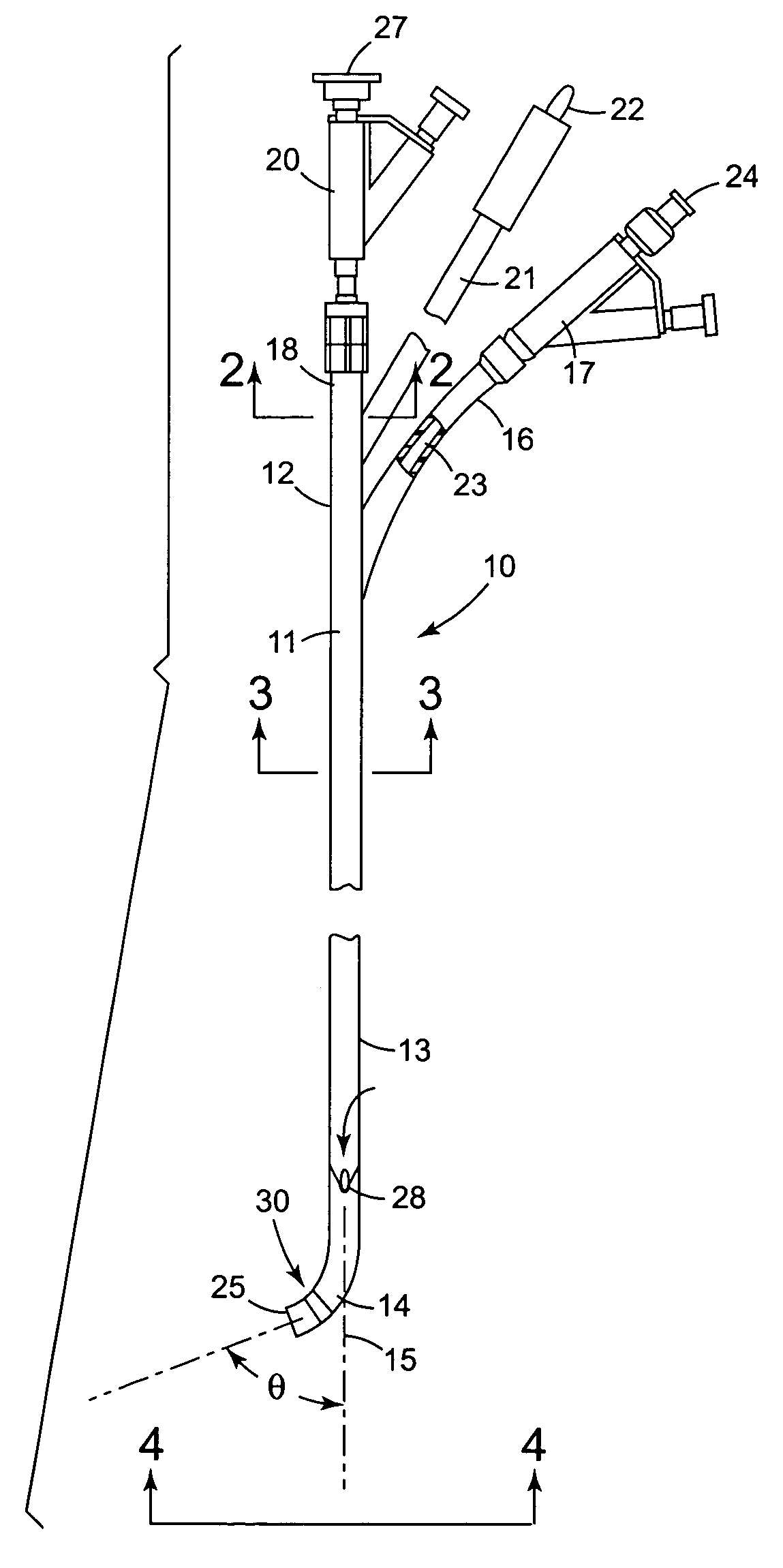
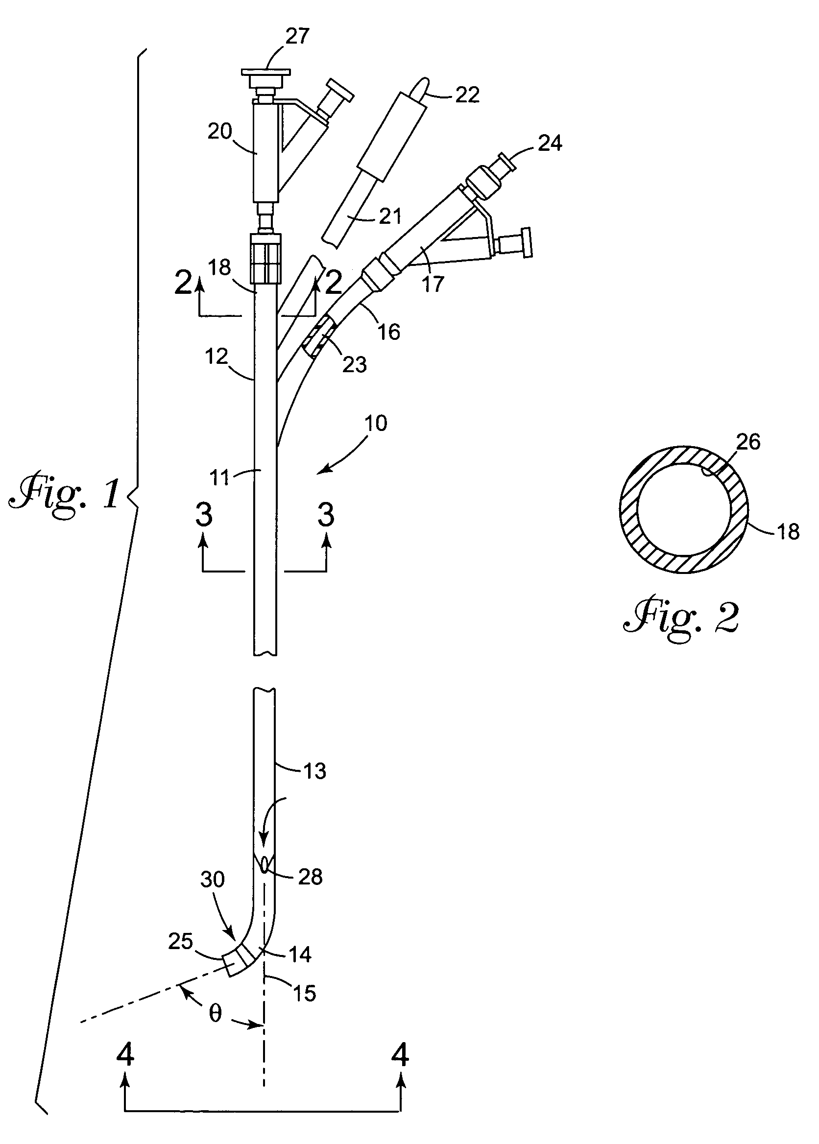
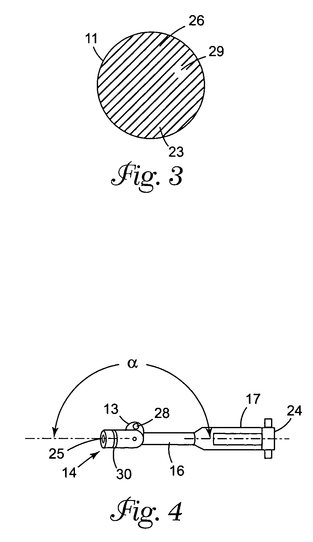
[0041]FIGS. 1 through 4 illustrate a tubular support member 10 embodying features of the invention which generally includes an elongated shaft 11 with a proximal shaft section 12, a distal shaft section 13 and a distal tip 14 which curves away from the longitudinal axis 15 an angle θ. The angle may vary depending upon the desired attack angle to the coronary sinus opening but generally will be from about 20° to about 70°, preferably about 30° to about 60°. The distal tip 14 may be preshaped with the prescribed angular orientation with respect to the longitudinal axis 15 or the tubular support member 10 may be provided with one or more control strands or wires (not shown) within the wall thereof which may be manipulated from the proximal end of the tubular member 10 to configure the distal tip to the desired shape after distal tip is disposed within the patient's right atrium.

[0042]The proximal shaft section 12 includes a first proximal extension 16 which has an adapter 17 on the pro...


PUM


Abstract

The invention is generally directed to an accessing system for a patient's coronary sinus which includes a tubular support member with a distal extremity extending into the right atrium of the patient's heart. A guide member is disposed within a first lumen of the tubular support member and advanced out an angled distal tip, through the patient's coronary sinus ostium and into the coronary sinus. A stabilizing member, similar to a conventional intravascular guidewire, is disposed within a second lumen of the tubular support member and extends into the right ventricle of the patient and is seated in the apex thereof. To advance the guide member into the CS ostium, the position of the distal extremity of the tubular support member is adjusted within the atrial chamber by moving longitudinally along or rotating about (or both) the stabilizing member and the guide member is advanced into the CS ostium. These steps may be repeated in a predetermined pattern in order to pass into the coronary sinus ostium.

Description

FIELD OF INVENTION[0001]The invention relates to the field of intravascular catheters, and particularly to a catheter suitable for accessing a patient's coronary sinus to facilitate delivery of therapeutic and diagnostic devices and agents.BACKGROUND OF THE INVENTION[0002]Congestive heart failure (CHF) is a condition in which the heart is unable to pump enough blood to meet the metabolic needs of a patient's body. The condition results in the patient having shortness of breath, weakness and a lack of stamina, fatigue, exercise intolerance and fluid retention which results from an inadequate flow of blood to the patient's kidneys. CHF is a progressive disease that involves the continuing enlargement of the heart muscle in response to the low blood output (cardiac output). The harder the heart works to pump more blood, the more enlarged it becomes. The more enlarged the heart becomes, the more work the heart must do to pump the same amount of blood. The progressive cycle of the diseas...

Claims


Application Information

Patent Timeline
IPC IPC(8): A61B18/18A61B18/04A61M25/00A61B18/00
CPCA61B17/3403A61B2017/00243A61M25/0169A61B2017/3492A61M25/0041A61B2017/003
Inventor WEBLER, WILLIAM E.
Owner CARDIAC PACEMAKERS INC
Learn More