Intravascular obstruction removing wire and medical instrument

Active Publication Date: 2006-05-09
TERUMO KK +1
View PDF29 Cites 169 Cited by
  • Summary
  • Abstract
  • Description
  • Claims
  • Application Information

AI Technical Summary

Benefits of technology

[0016]It is an object of the present invention to provide an intravascular obstruction removing wire and medical instrument whi

Problems solved by technology

With the thrombolytic agent, however, sometimes thrombolysis takes time.
These apparatuses have a complicated structure and a large diameter, and are used alone or require a thick guide catheter.
With the structure of this apparatus, it is difficult to hold a thrombus that blocks up a blood vessel.
More specifically, a central wire and helical loops cannot form a large holding space, but can merely provide a narrow space where the sheared tissue is to be held.
Due to the presence of the central wire, a thrombus cannot be easily accommodated in the helical loops.
Although this instrument is suitable for holding a thin, elongated rod-like obstruction, it is difficult for this instrument to grip an obstruction such as a thrombus which is slippery.
Although this instrument can be theoretically used, it is difficult to hold an obstruction with the instrument exc

Method used


Image

  • Intravascular obstruction removing wire and medical instrument
  • Intravascular obstruction removing wire and medical instrument
  • Intravascular obstruction removing wire and medical instrument

Examples


first embodiment

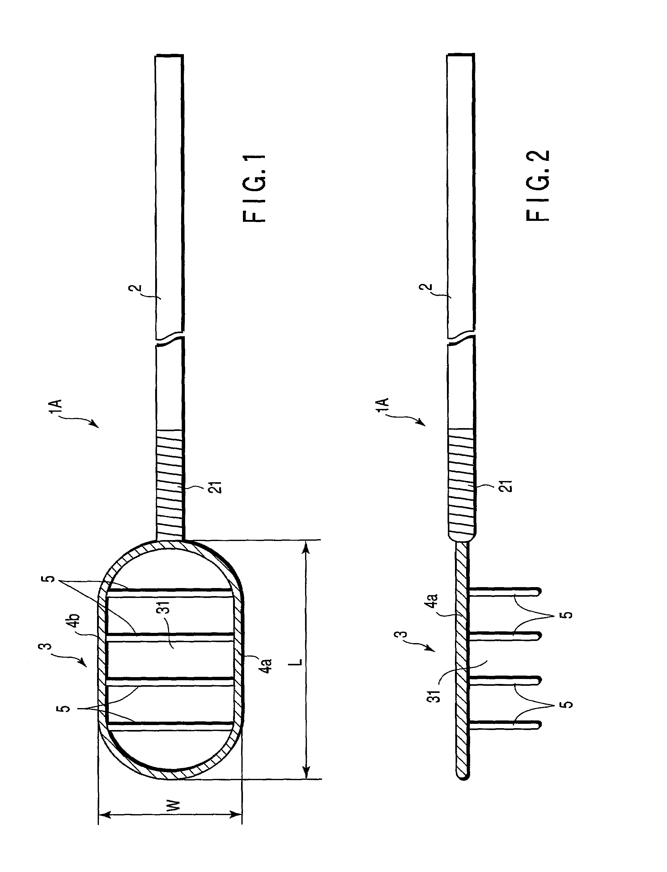
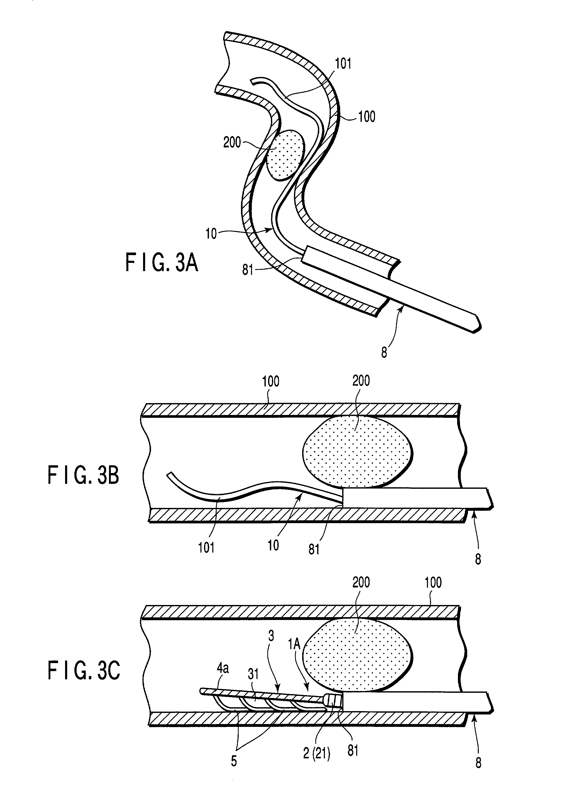
[0036]First, the first embodiment will be described with reference to FIGS. 1 to 3D. In the following description, the upper side and lower side are respectively called “the proximal end” and “distal end” in FIGS. 1 and 2. The right side and left side are respectively called “the proximal end” and “distal end” in FIGS. 3A to 3D. Generally, the proximal end side of the wire is maintained outside the human body, and the distal end thereof is inserted in a blood vessel of the human body.

[0037]An intravascular obstruction removing wire 1A shown in FIGS. 1 and 2 serves to trap and remove an obstruction (to be referred to as “embolus” hereinafter) such as a thrombus or clot in the blood vessel, that causes embolism.

[0038]The intravascular obstruction removing wire 1A has an elongate wire body 2 and a trapping portion 3. The trapping portion 3 is formed or provided at the distal end of the wire body 2 and can trap an embolus in the blood vessel. The wire body 2 has appropriate rigidity and...

third embodiment

[0087]An intravascular obstruction removing wire according to the present invention will be described with reference to FIGS. 7 to 10.

[0088]An intravascular obstruction removing wire 1C according to this embodiment is substantially identical to that of the first embodiment except that the shape of its trapping portion 3 is different.

[0089]In the trapping portion 3, non-branched wire portions 4a and 4b and filament portions 5 are formed of a plurality of (six in this embodiment) loop wires 6 having loop portions of almost the same sizes which are formed at the distal end of a wire body 2 to form loops (rings). The proximal ends of the loop wires 6 are overlaid vertically, i.e., in one direction, as best shown in FIG. 9. As the proximal ends of the respective loop wires 6 enter a catheter 8, they are gradually displaced in an inner direction to narrow the interval between them. Thus, forces that fasten an embolus 200 inwardly act, so the embolus 200 can be gripped between the opposite...

fourth embodiment

[0097]the present invention will be described with reference to FIGS. 11 to 13.

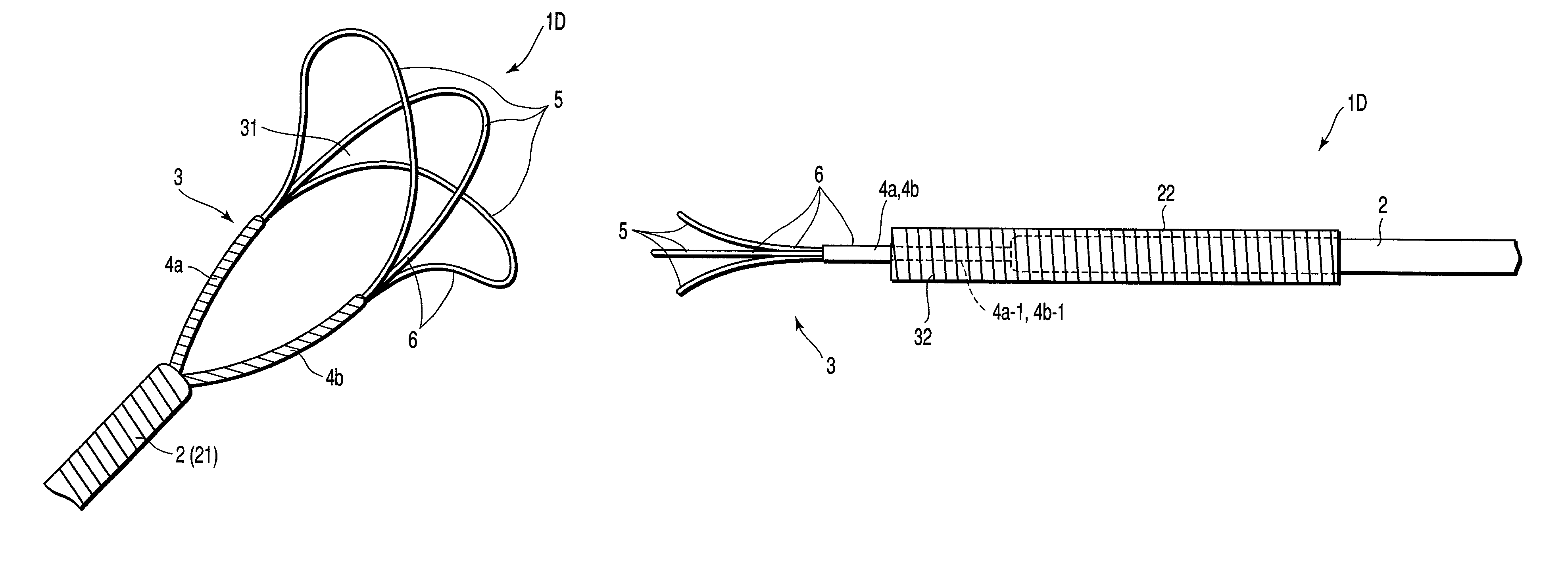
[0098]As shown in FIGS. 11 and 13, a trapping portion 3 in an intravascular obstruction removing wire 1D according to this embodiment is formed of a plurality of (three in this embodiment) loop wires 6, in the same manner as in the third embodiment. With the loop wires 6, non-branched wire portions 4a and 4b are formed by twisting the proximal end portions of the loop wires, having a predetermined length s as shown in FIG. 12. More specifically, the proximal end portions on one side of the plurality of loop wires 6 are twisted integrally to form one wire portion 4a, while the proximal ends on the other side are thereof twisted integrally to form the other wire portion 4b. Each of wire portions 4a, 4b has a length s as shown in FIG. 12.

[0099]Of three filament portions 5, one located at the center is located on almost the same plane as the non-branched wire portions 4a and 4b, that is, this filament portion...


PUM


Abstract

An intravascular obstruction removing wire includes an elongate wire body, at least two non-branched wire portions having distal ends and proximal ends which are connected to a distal end of the wire main body, and a plurality of filament portions extending across the wire portions. The non-branched wire portions and the filament portions form a trapping portion. The trapping portion is deformable from a large-diameter state in which the non-branched portions branch to the distal end of the wire body forward in different directions and the filament portions are separated from each other, so that a space surrounded by the non-branched wire portions and the filament portions is formed to trap therein an obstruction in a blood vessel, to a small-diameter state in which the non-branched wire portions are positioned so that a distance between the wire portions is smaller than that of the wire portions in the large-diameter state.

Description

CROSS-REFERENCE TO RELATED APPLICATIONS[0001]This application is based upon and claims the benefit of priority from the prior Japanese Patent Application No. 2001-201331, filed Jul. 2, 2001, the entire contents of which are incorporated herein by reference.BACKGROUND OF THE INVENTION[0002]1. Field of the Invention[0003]The present invention relates to an intravascular obstruction removing wire and medical instrument for removing an obstruction, for example, an embolus in a blood vessel.[0004]2. Description of the Related Art[0005]Death cases and sequelae caused by strokes increase in recent years, and postapoplectic therapy needs to be established as soon as possible. As a typical postapoplectic treatment, a thrombolytic treatment using a thrombolytic agent has been developed to treat acute cerebral infarct, and has achieved a satisfactory treatment effect. With the thrombolytic agent, however, sometimes thrombolysis takes time. A thrombus which is reduced in size may be scattered t...

Claims


Application Information

Patent Timeline
IPC IPC(8): A61M29/00A61B17/22
CPCA61B17/221A61B2017/2212
Inventor GOTO, KATSUYAKANEKO, TAKASHIKANAMARU, TAKESHITAKEUCHI, MASAHIROOKADA, KEIJI
Owner TERUMO KK
Why Eureka
Try Eureka