Multirotation type encoder

a multi-rotation type, encoder technology, applied in the direction of mechanical conversion of sensor output, code conversion, instruments, etc., can solve the problems of complicated mechanism, and large-scale formation of apparatus, and achieve high reliability, long life, and high reduction ratio

Inactive Publication Date: 2006-05-09
YASKAWA DENKI KK
View PDF13 Cites 21 Cited by
  • Summary
  • Abstract
  • Description
  • Claims
  • Application Information

AI Technical Summary

Benefits of technology

[0005]Hence, in view of the above-described drawback of the related art, an object of the present invention is to provide a multirotation type encoder which is small-sized even in the case in which the multirotation transmitting portion is at a high reduction ratio, having no mechanical contact portion other than a bearing, having high reliability and long life and dispensing with interchange of a battery.

Problems solved by technology

However, since the related art is provided with a mechanical multirotation transmitting mechanism, in order to increase the reduction ratio, the diameter of the driven gear needs to be significantly increased relative to the diameter of the driving gear and there poses a problem of bringing about large-sized formation of the apparatus, and even when a set of gears having small reduction ratios is constituted in multistage, there poses a problem that the mechanism is complicated and large-sized formation of the apparatus is brought about.
Further, in bringing the gears in mesh with each other, there poses a problem that an error is produced at a rotation detector by backlash or wear of meshed faces or a problem that reliability is deteriorated.
Furthermore, since the rotational angle is detected by counting teeth numbers of the gears at respective stages and therefore, there poses a problem that an electronic part and a battery are needed for storing a count number and cost and time are needed for interchanging the battery periodically.

Method used


Image

  • Multirotation type encoder
  • Multirotation type encoder
  • Multirotation type encoder

Examples


first embodiment

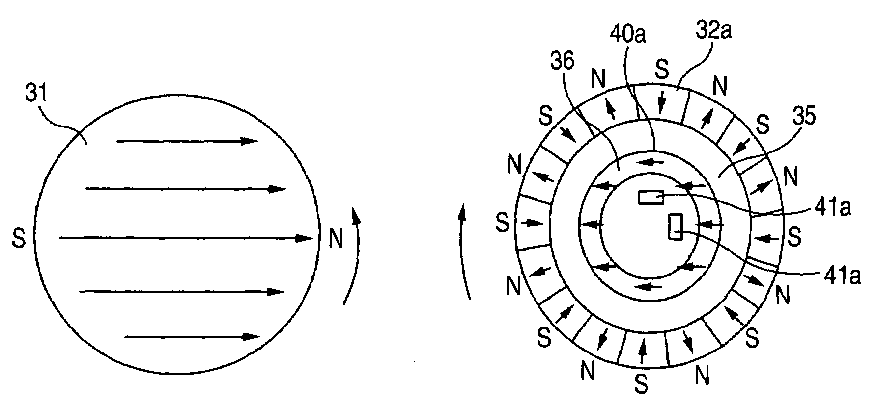
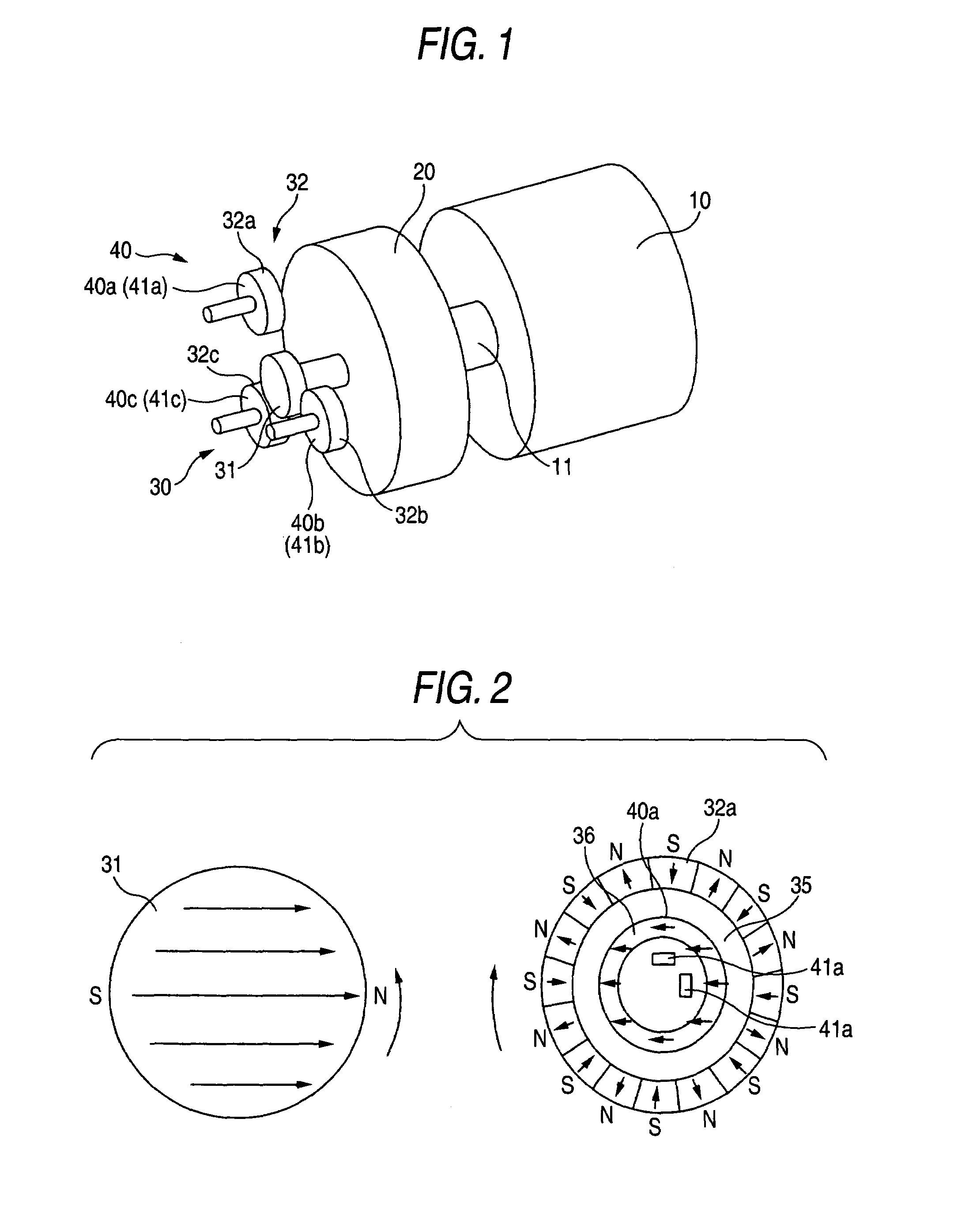
[0033]FIG. 1 shows a first embodiment of the invention. FIG. 1 is a perspective view of a multirotation type encoder showing the first embodiment of the invention. In the drawing, numeral 20 designates a first encoder for detecting an absolute value angle, numeral 30 designates a speed reducing mechanism comprising a first magnetic gear 31 and a second magnetic gear 32, numeral 40 designates a second encoder, and numeral 41 designates first magnetic field detecting means. FIG. 2 illustrates schematic views of the magnetic gears of the speed reducing mechanism 30. FIG. 2(a) shows the first magnetic gear 31 of FIG. 1 and FIG. 2(b) shows the second magnetic gear 32 thereof. An arrow mark in the drawings indicates a magnetizing direction. Meanwhile, the second magnetic gear 32 is magnetized in a circumferential direction at a number of portions thereof.

[0034]The first magnetic gear 31 having a diameter of 5 mm is magnetized in 2 poles in a direction orthogonal to a rotating shaft. The d...

second embodiment

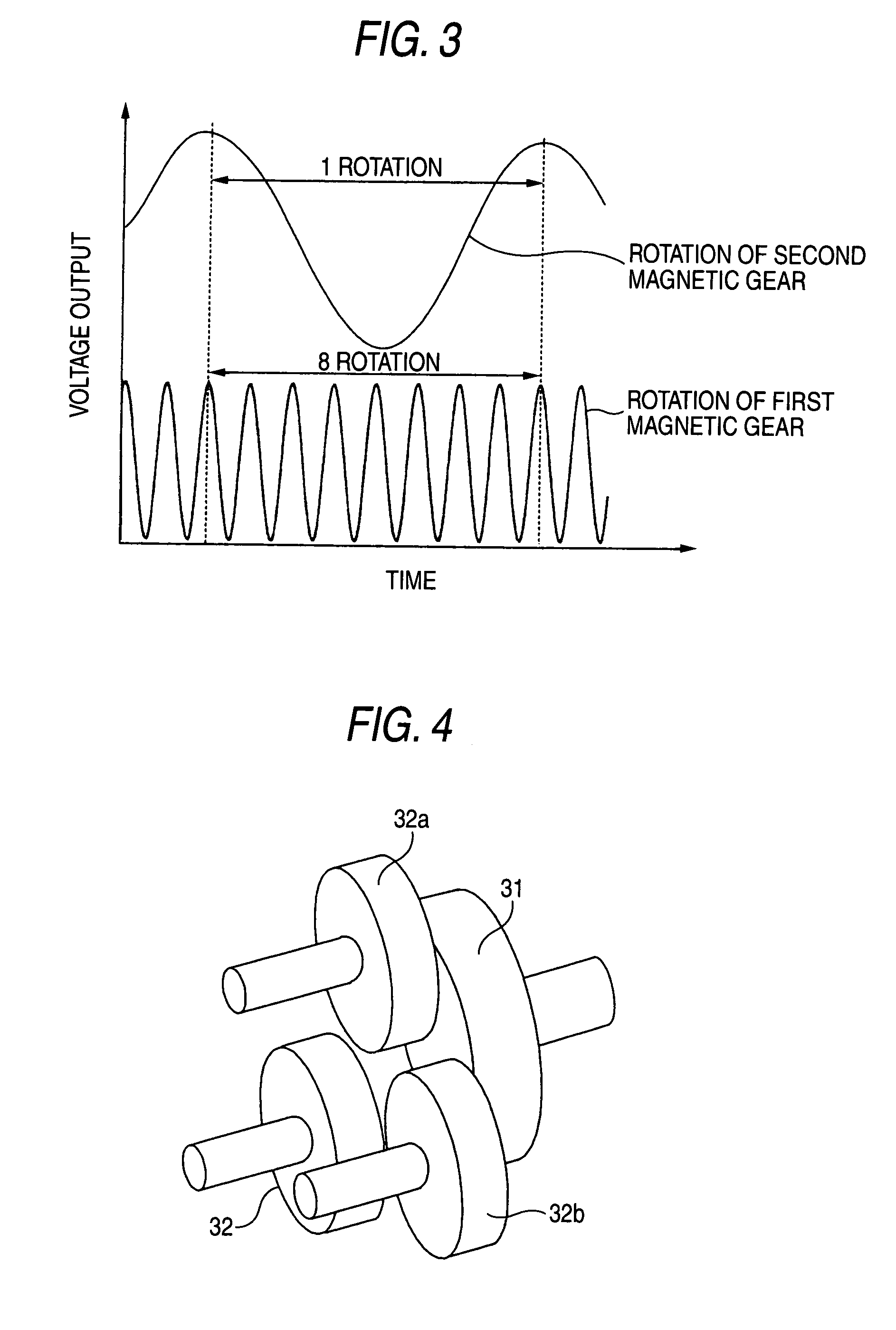
[0040]FIG. 4 shows a second embodiment of the invention. FIG. 4 is a perspective view of a magnetic coupling portion comprising magnetic gears showing a second embodiment of the invention.

[0041]A second magnetic gear 32 is arranged relative to a first magnetic gear 31 to overlap each other in an axial direction via an air gap. The first magnetic gear 31 is magnetized in a longitudinal direction of a rotating shaft and a number of poles thereof is 2 poles. Also the second magnetic gear 32 is magnetized in a longitudinal direction of a rotating shaft and multiple poles are magnetized in a circumferential direction. Therefore, when portions of the first magnetic gear 31 and the second magnetic gear 32 having different polarities are opposed to each other, an attracting force is operated therebetween, a transmitting force is constituted thereby, and rotation of the first magnetic gear 31 is transmitted to the second magnetic gear 32. Although operation and effect thereof are similar to ...

third embodiment

[0042]FIG. 5 shows a third embodiment of the invention. FIG. 5 is a perspective view of a multirotation type encoder showing the third embodiment of the invention. In the drawing, notations 33, 33a, 33b, 33c designate third magnetic gears, notations 42, 42a, 42b, 42c designate second magnetic field detecting means, and notations 50, 50a, 50b, 50c designate second rotating shafts for connecting the second magnetic gear 32 and the third magnetic gear 33. All of the magnetic gears are rotatably supported by bearings, not illustrated, via the second rotating shaft 50. The third magnetic gear 33 is magnetized orthogonally to the rotating shaft 50 and in one direction. Further, 2 pieces or more of the second magnetic field detecting means 42 are arranged at a surrounding of the third magnetic gear 33.

[0043]Next, an explanation will be given of a method of detecting a rotational angle of the second magnetic gear 32. When the third magnetic gear 33 is rotated simultaneously with the second ...


PUM


Abstract

A multirotation type encoder of the invention includes a first encoder 20 attached to a rotating shaft 11 of a rotating machine 10 for detecting an absolute value rotational angle within one rotation, and a second encoder for counting a multirotation amount of the rotating shaft 11 by using a speed reducing mechanism 30 by magnetic coupling and the second encoder 40 is constituted by a first magnetic gear 31 directly connected to the rotating shaft and magnetized in multiple poles and at least one second magnetic gear 32 arranged to be opposed thereto in noncontact and magnetized in multiple poles by a number of magnetic poles larger than that of the first magnetic gear 31 and is constituted to count a multirotation amount by detecting a rotational angle of the second magnetic gear by the second encoder.

Description

TECHNICAL FIELD[0001]The present invention relates to a batteryless multirotation type encoder for detecting the amount of multirotation of a servomotor used for a robot, a machine tool or the like by an absolute value angle.RELATED ART[0002]There is a multirotation type encoder of a related art as shown by FIG. 12. FIG. 12 is a perspective view showing the multirotation type encoder of the related art. In the drawing, numeral 10 designates a rotating machine, numeral 20 designates a first encoder and numeral 40 designates a second encoder. A rotating shaft 12 of the first encoder 20 is attached with a driving gear 34a and the gear 34a is coupled to a driven gear 34b. The gear 34b is coupled to the second encoder 40 via a rotating shaft 13.[0003]According to the multirotation type encoder constituted in this way, when the rotating machine 10 is rotated, the second encoder 40 is transmitted with a rotational number reduced in accordance with a reduction ratio determined by a ratio of...

Claims


Application Information

Patent Timeline
Patent Type & Authority Patents(United States)
IPC IPC(8): G01B7/30G01D5/04G01D5/245
CPCG01D5/04G01D5/2451G01D5/245G01D2205/28G01D2205/26
Inventor KABASHIMA, TAKEFUMIMATSUZAKI, KAZUNARIUEMURA, KOJINAGASE, TAKASHI
Owner YASKAWA DENKI KK
Why Eureka
Try Eureka