
VCO with power supply rejection enhancement circuit

a power supply and enhancement circuit technology, applied in the direction of oscillator generators, pulse automatic control, electrical equipment, etc., can solve the problems of large variation of the output signal, affecting the performance of the control and output signal, and affecting the output signal. , to achieve the effect of reducing the noise componen

Active Publication Date: 2006-05-09
AVAGO TECH INT SALES PTE LTD
View PDF8 Cites 15 Cited by
  • Summary
  • Abstract
  • Description
  • Claims
  • Application Information

AI Technical Summary

Benefits of technology

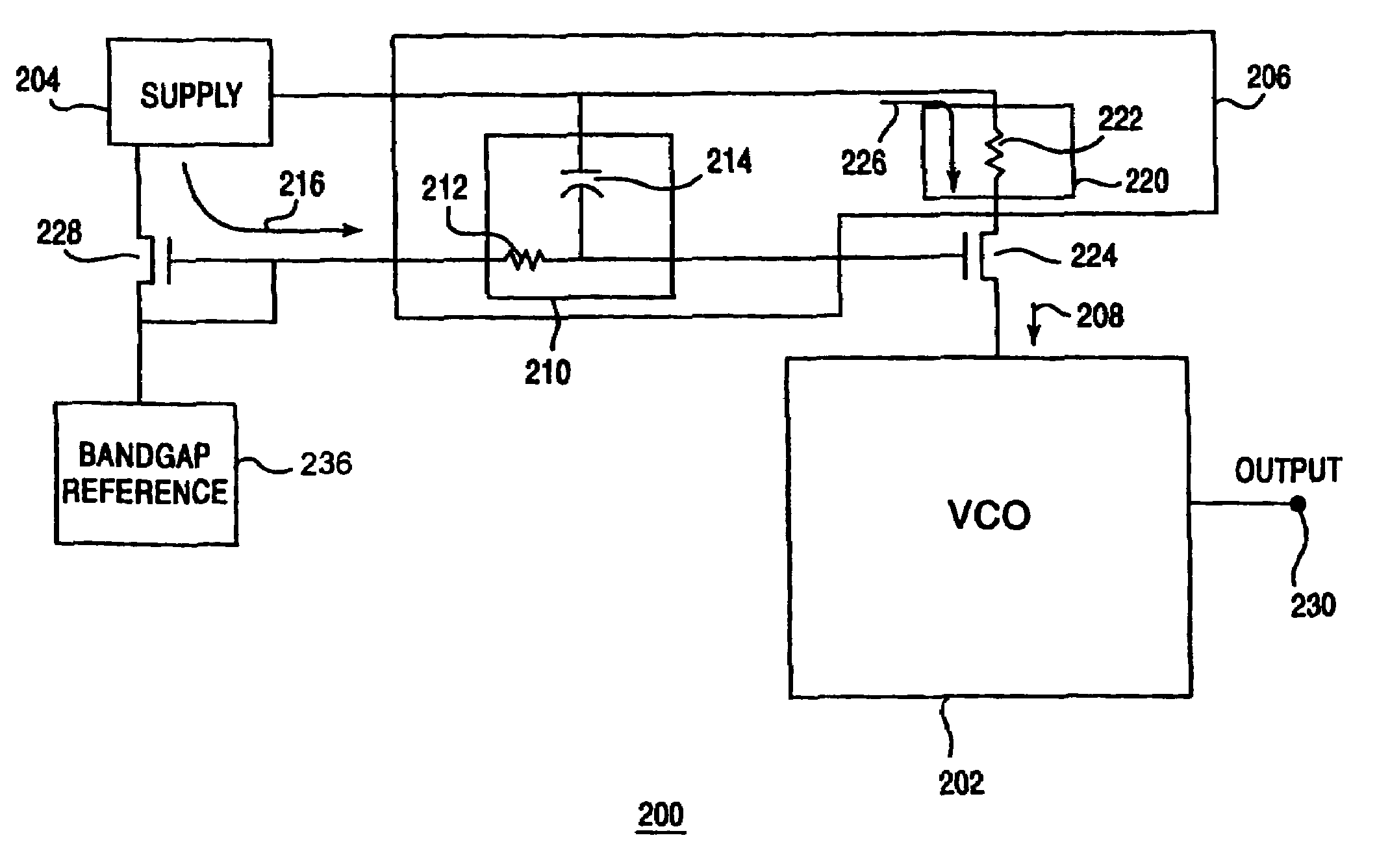
The invention is about a circuit and system for reducing noise in an oscillating circuit. The circuit includes a noise reduction circuit with a filter and a degeneration circuit to filter out bias noise and reduce the gain in the current source. The system also includes a filtering device and a degeneration device to filter out bias and supply noise, respectively. The method involves filtering the bias noise and reducing the supply noise by passing the current or bias current through the noise reduction circuit. The circuit and system can improve the accuracy and stability of the output signal from the oscillating circuit.

Problems solved by technology

Noise within circuits operating at high frequency can impede performance and degrade the control and output signals.
For example, noise in the input signal may result in large variations of the resulting output signal.
This action, in turn, degrades performance of any circuit, detector, carrier, transmitter device and the like using the VCO circuit.
Input noise may arrive at the VCO from a coupled power supply or other components, either in the current or voltage.
In a fully integrated chip, the power supply, or the chip itself can be noisy.
This noise may occur when the current source is also connected to a current mirror, or bandgap reference.
This cross connection produces noise that is then input into a gate coupled to the VCO circuit.
Thus, noise is a critical factor in VCO circuits, particularly those that operate at high frequencies.
Further, supply and bias noise is introduced to the input signals to impede the input signals.

Method used


Image

  • VCO with power supply rejection enhancement circuit
  • VCO with power supply rejection enhancement circuit
  • VCO with power supply rejection enhancement circuit

Examples


Embodiment Construction

[0020]Reference will now be made to the disclosed embodiments of the present invention, examples of which are illustrated in the accompanying drawings.

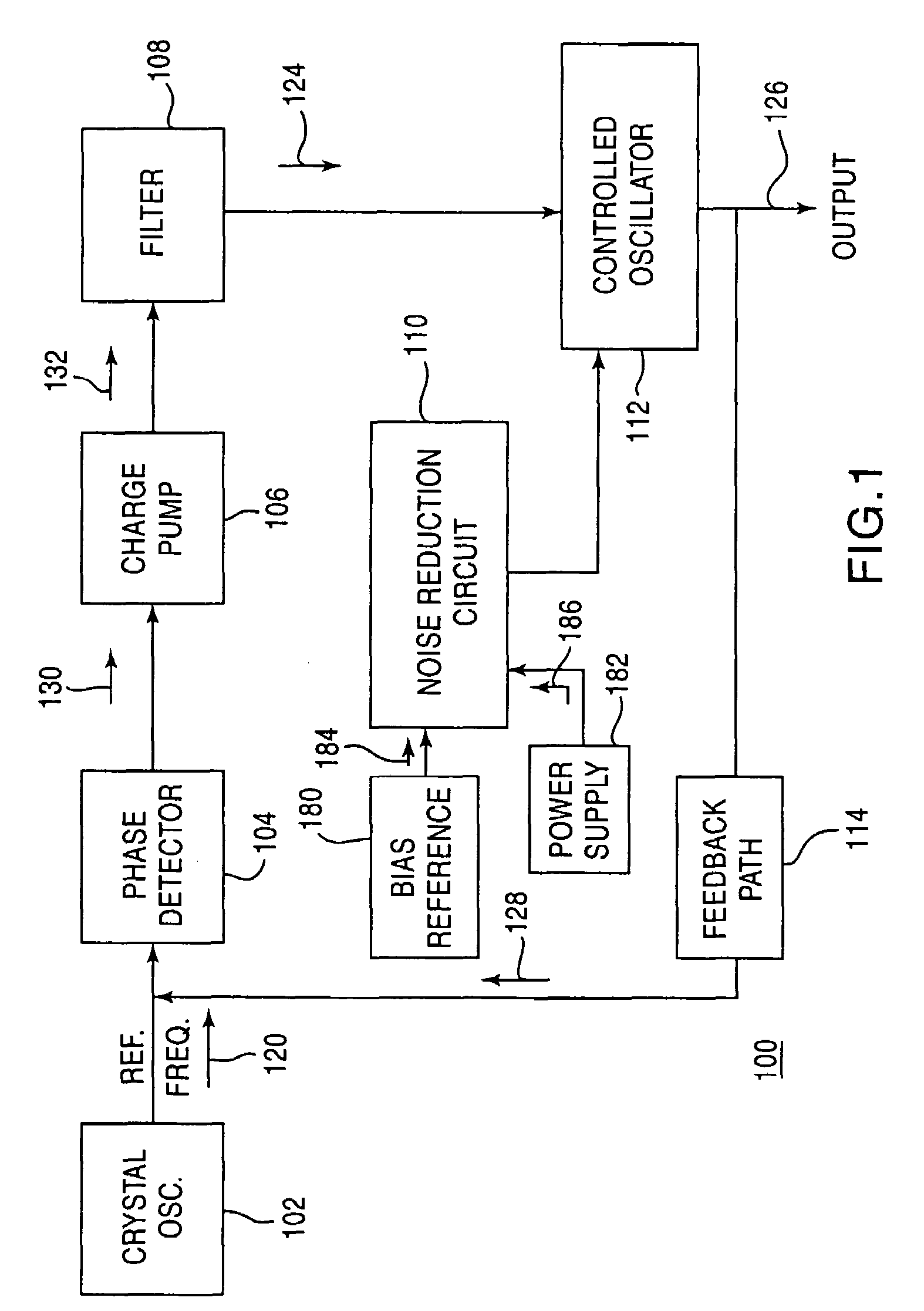
[0021]FIG. 1 depicts a block diagram of a phase locked loop (PLL) 100 having noise reduction circuit 110 according to the preferred embodiments. PLL 100 may be a circuit configured to provide an output signal 126. PLL 100 may be used in a variety of communication devices using one or more local oscillators. PLL 100 may be implemented in a conventional PLL or produce a local oscillation from a reference frequency.

[0022]In one example, PLL 100 includes crystal oscillator 102 that generates reference frequency signal 120. Reference frequency signal 120 is input into phase detector 104, along with feedback signal 128. Phase detector 104 may detect the difference between reference frequency signal 120 and feedback signal 128. A differential signal 130 is generated by phase detector 104 to indicate the difference between reference frequency...


PUM


Abstract

An oscillating circuit having a noise reduction circuit is disclosed. The noise reduction circuit is coupled to the current source for the oscillating circuit. The noise reduction circuit reduces a bias noise component from a bias current, and a supply noise component from a supply current. The noise reduction circuit is coupled to the current source at a gate and a supply for the current source. The noise reduction circuit includes a filter coupled to the gate of the current source that reduces the bias noise component. The noise reduction circuit also includes a degeneration circuit coupled to the supply of the current source that reduces the supply noise component. The current source generates an input signal to control the oscillating circuit with reduced noise.

Description

BACKGROUND OF THE INVENTION[0001]1. Field of the Invention[0002]The present invention relates to controlled oscillators, and more particularly, the present invention relates to a controlled oscillator that provides an output frequency controlling signal subject to a noise reduction circuit.[0003]2. Description of the Related Art[0004]The use of wireless communication applications for in-home, in-building networks and direct communications is increasing. These applications modulate data onto at least one carrier and transmit data as a modulated signal via a transmitter. A receiver receives the frequency modulated signal, and demodulates it to recapture the data.[0005]In the various stages of transmitting and receiving signals, local oscillators generate signals that result in an output frequency. Sometimes the desired frequency may vary. Variable frequency oscillators are tunable oscillators that receive a fixed frequency that is output over a selectable wide range of frequencies. To...

Claims


Application Information

Patent Timeline
Patent Type & Authority Patents(United States)
IPC IPC(8): H03B1/04H03L5/00H03B5/04
CPCH03B5/04
Inventor CHIEN, HUNG-MING
Owner AVAGO TECH INT SALES PTE LTD
Learn More