Mechanically rotatable wireless RF data transmission subscriber station with multi-beam antenna

Active Publication Date: 2006-05-09
NETGEAR INC
View PDF18 Cites 51 Cited by
  • Summary
  • Abstract
  • Description
  • Claims
  • Application Information

AI Technical Summary

Benefits of technology

[0007]The present invention is directed to a wireless RF data transmission subscriber station with integrated multibeam antenna. The subscriber station is preferably an indoor or outdoor mounted data transceiver with integral antenna array, RF and IF electronics, digital signal processing electronics and power supply. Preferably, the present subscriber station is mechanically, rotatable and employs a multibeam antenna array. There are no external connections between the antenna array and the RF electronics. An integral or integrated approach to the antenna and the radio is employed. The present invention reduces the number of enclosures for an RF data subscriber station to make the subscriber station more compact and lower cost. Also, a more modular design eases user installation of such a subscriber unit. The present subscriber station helps reduce the costs of installation by providing an integrated unit that is installed in the end user's space, rather than on top of a building. Furthermore, this would facilitate rapid implementation of the system. Additionally, the present invention can be easily deployed to provide wireless RF data communication due at least in part to elimination of coax or waveguide connections from the antenna to the radio.

Problems solved by technology

Interconnecting cables between such units disposed in separate enclosures is problematic.
Both of these connection media suffer from a common problem, moisture ingress.
Moisture is very lossy at microwave frequencies.
Another problem associated with the use of multiple enclosure units is the fairly complex level of technical skill necessary to install the separate units.
The time invested and / or the hourly rate of a technician necessary to properly install such a prior art configuration is considerable.
With prior art physically separate components additional costs may be associated with locating one or more antennas on the roof of a building.
Additionally, prior art fixed data subscriber antennas fail to provide flexibility to change base stations as interference and line of sight changes dictate.
This also further limits the placement of a data subscriber antenna as a fixed antenna would always require a clear line of sight to the base station to which it is linked.
Further, the use of multiple enclosures as discussed above may render a prior art data subscriber station too bulky or impractical for installation in a user's space.
Where movable antennas have been employed, such as in radar, the technology suffers from disadvantages.
Though these two sub-enclosures may reside together on a common structure defining the overall device, the sub-enclosures have disparate and incompatible functions, one being to protect the moving antenna from weather and the other to dissipate heat.
The bulkiness of this packaging generally forces separation of the electronics and the radome entirely.

Method used


Image

  • Mechanically rotatable wireless RF data transmission subscriber station with multi-beam antenna
  • Mechanically rotatable wireless RF data transmission subscriber station with multi-beam antenna
  • Mechanically rotatable wireless RF data transmission subscriber station with multi-beam antenna

Examples


Embodiment Construction

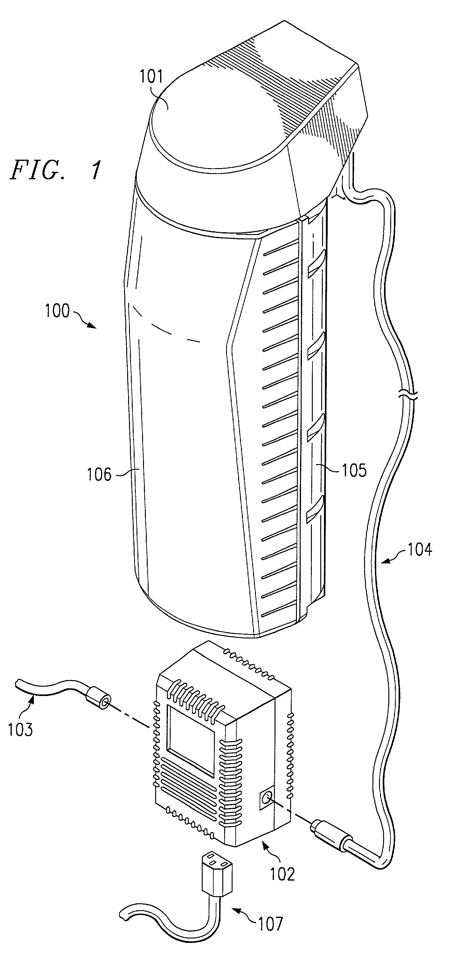
[0022]Turning to FIG. 1, subscriber station 100 is a rotatable integrated RF / electronics unit and multi-beam antenna array, shown suspended from a preferred overhead mounting bracket 101. Separate transformer / LAN block 102 may provide Ethernet connection 103 to subscriber equipment and a combined power / LAN signal connection to subscriber station 100 via line or cable 104. Subscriber station 100 has mechanical functions and is weatherized, facilitating its use indoors or out.

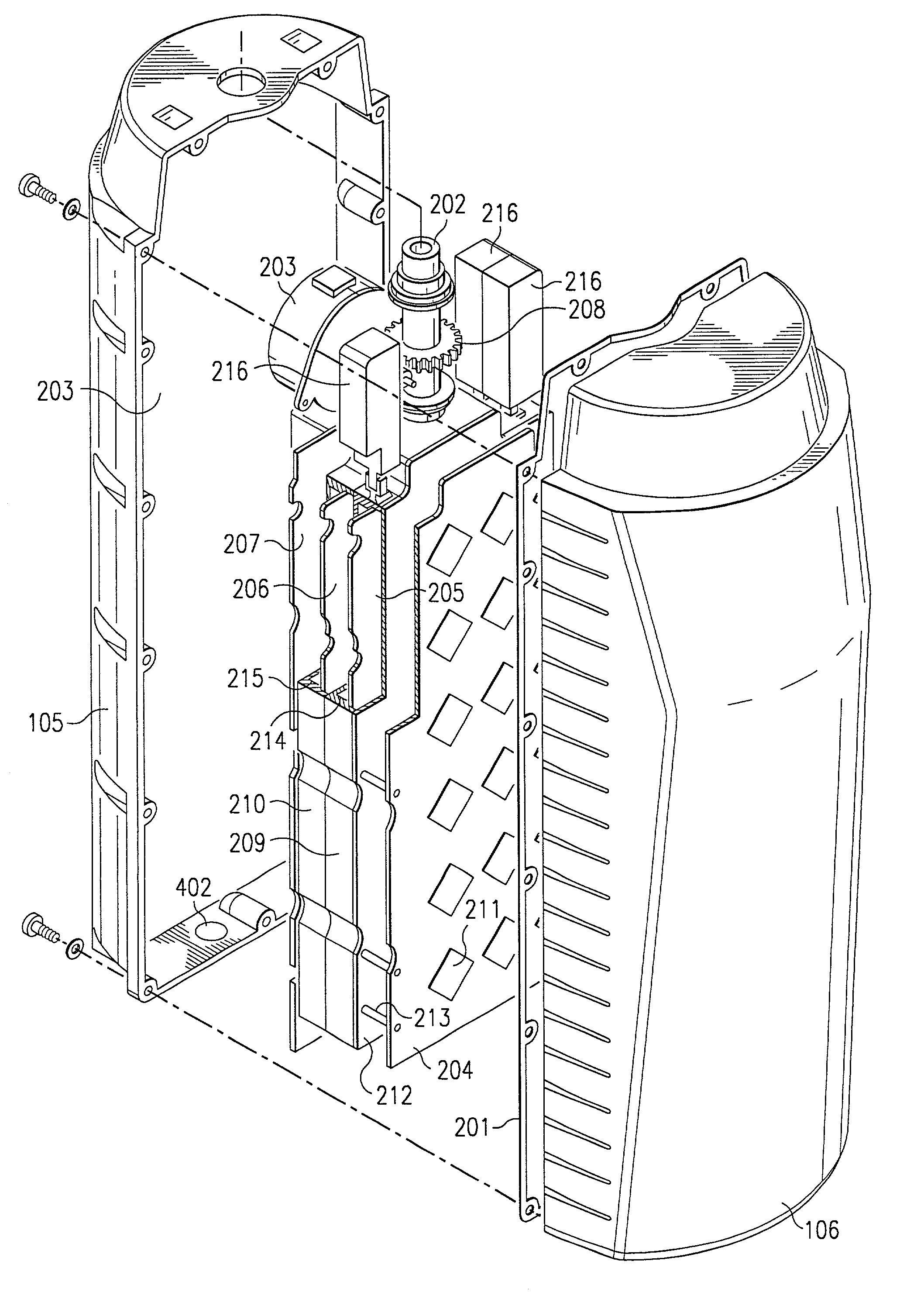
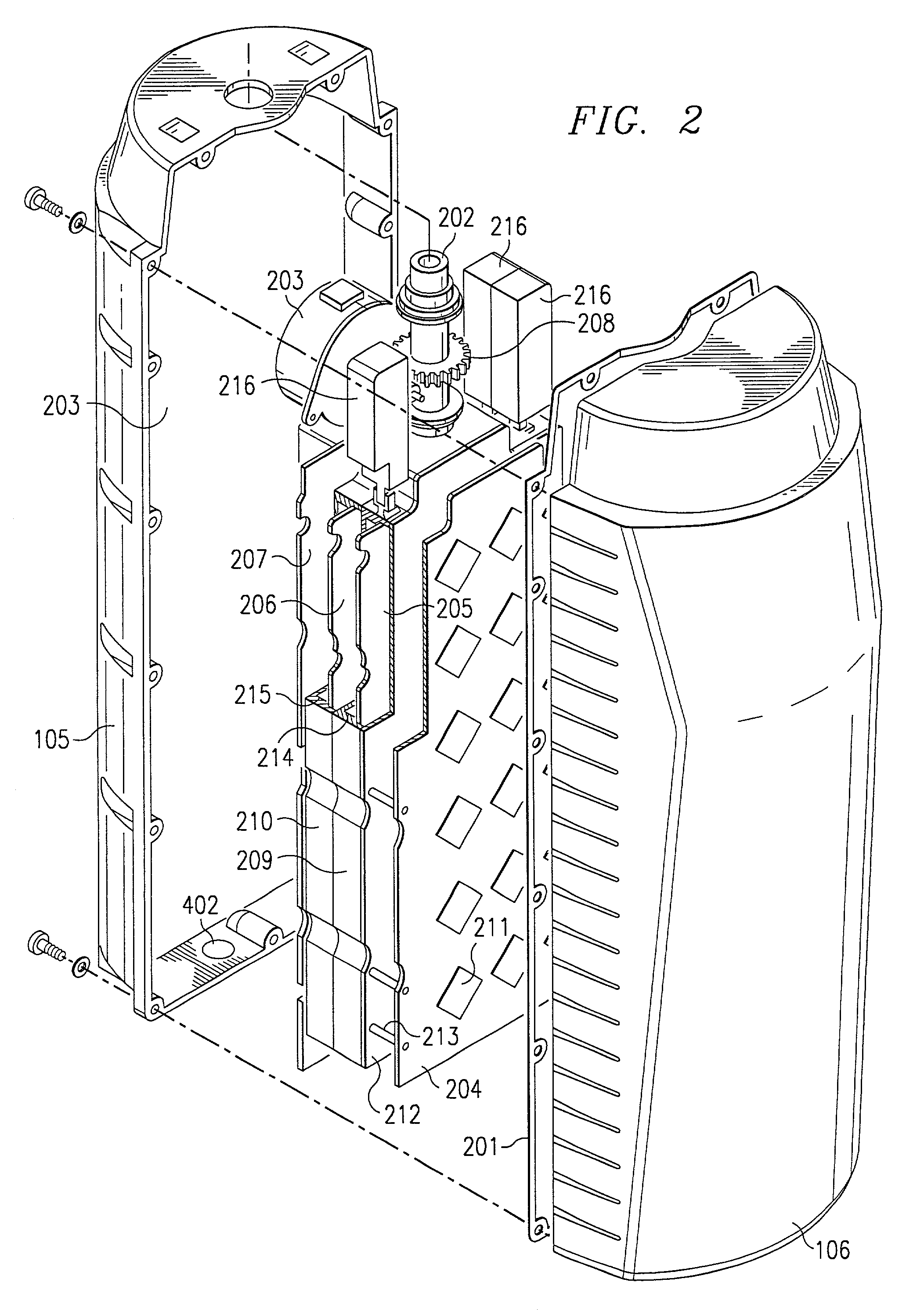
[0023]Turning to FIGS. 2 and 3, the exterior of subscriber station 100 preferably comprises die cast rear housing 105 and resilient injection molded radome 106. Preferably, housing 105 is cast from aluminum or magnesium and also provides heavily finned heat sink 301 for heat dissipation via fins 302. Preferred embodiments of housing 105 and radome 106 have a robust closure detail preferably including weather-proof carbon impregnated gasket 201 captured between rear housing 105 and radome 106 at the interface seal...


PUM


Abstract

A wireless RF data transmission system subscriber station has a fixed, overhead bracket secured, spindle. An open sided housing is rotatably mounted to the spindle. The housing has a finned heat sink and is interiorly coated with heat absorbing paint. Emissions shielding enclosures secured within the housing house an RF transceiver. An antenna array mounted to an enclosure is operatively connected to the transceiver through the enclosures for communicating RF data signals. An A / D-D / A board is mounted to an enclosure on an opposite side from the array. A radome is secured over a face of the array, sealed to the housing by a carbon impregnated gasket. An electric motor mounted within the housing and operatively engaging the spindle is controlled by antenna aiming logic for aiming the station and its array. An orifice sealed with a waterproof, breathable membrane allows moisture to escape the housing and prevents moisture infiltration.

Description

FIELD OF THE INVENTION[0001]The present invention generally relates to wireless RF data communication. Specifically, the present invention relates to a mechanically rotatable multi-beam subscriber station transceiver and antenna.BACKGROUND OF THE INVENTION[0002]Prior art microwave and data communications subscriber equipment in point to point or point to multipoint RF data transmission systems has typically been housed in separate enclosures. Generally, a prior art wireless RF data transmission subscriber station would consist of an antenna comprising one outdoor enclosure. A radio and RF to IF converters would be in at least one other enclosure, which might be outdoors. An indoor unit for a third enclosure maybe include IF to RF converts as well as analog to digital (A / D) and digital to analog (D / A) converters. A fourth unit would be a power supply to power the other units.[0003]Interconnecting cables between such units disposed in separate enclosures is problematic. The prior art ...

Claims


Application Information

Patent Timeline
IPC IPC(8): H04M1/00H01Q1/24
CPCH01Q1/246H01Q1/42H01Q1/02H01Q21/065H01Q25/005H01Q3/04
Inventor SHIELDS, RICHARD A.KARR, RANDY J.DEMARIA, JAMES E.GREEN, CARTER K.PERRIGO, GREGORY D.COBB, BARRY S.OLSON, KENT W.REUDINK, MARK D.
Owner NETGEAR INC
Why Eureka
Try Eureka